Remove Blanking Panels
You must remove the half-height blanking panels covering the upper and lower chassis slots, if installed.
Step 1
Identify the chassis slots in which the full-height line card will be installed.
Step 2
Use a Phillips #2 screwdriver to loosen the screws at the top and bottom of the blanking panel. Hold the screws on the
blanking panel, and pull the blanking panel away from the chassis to expose the chassis slot.
Step 3
Repeat step 2 to remove the half-height blanking panel covering the chassis slot directly below the slot exposed in the
previous step.
On a powered up chassis, do not leave chassis slots uncovered for extended periods of time. This reduces
airflow through the chassis, which could cause it to overheat. Install a card or a blanking panel s in every
chassis slot.
Caution
Remove the Half-Height Card Guide
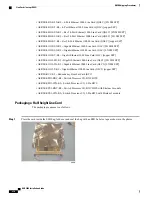
You must next remove the half-height card guide separating the exposed upper and lower chassis slots.
Figure 70: Half-height Card Guide
ASR 5000 Installation Guide
260
Preparing a Full-Height Line Card Slot
Remove Blanking Panels
Содержание ASR 5000
Страница 16: ...ASR 5000 Installation Guide xvi About this Guide Contacting Customer Support ...
Страница 64: ...ASR 5000 Installation Guide 48 Installation Procedure Overview Laser Notice ...
Страница 100: ...ASR 5000 Installation Guide 84 Line Card Installation Installing the XGLC ...
Страница 118: ...ASR 5000 Installation Guide 102 Cabling the Switch Processor Input Output Line Card Central Office Alarm Wiring Example ...
Страница 122: ...ASR 5000 Installation Guide 106 Cabling the Fast Ethernet 10 100 Line Card FLC2 Interfaces ...
Страница 136: ...ASR 5000 Installation Guide 120 Cabling the Optical ATM Line Cards Cabling the Optical SFP Interface ...
Страница 140: ...ASR 5000 Installation Guide 124 Cabling the Channelized Line Cards Cabling the Optical SFP Interface ...
Страница 144: ...Figure 49 PFU Wiring Diagram ASR 5000 Installation Guide 128 Cabling the Power Filter Units Power Cable Requirements ...
Страница 148: ...ASR 5000 Installation Guide 132 Cabling the Power Filter Units Connecting the PFU to the Power Source ...
Страница 206: ...ASR 5000 Installation Guide 190 Removing and Installing SMC PC Cards Removing PC Cards ...
Страница 212: ...ASR 5000 Installation Guide 196 Replacing the Chassis Air Filter Installing the Air Filter ...
Страница 220: ...ASR 5000 Installation Guide 204 Replacing a Power Filter Unit What to do with the Failed PFU ...
Страница 266: ...ASR 5000 Installation Guide 250 Safety Electrical and EMC Certifications Korean EMC ...
Страница 270: ...ASR 5000 Installation Guide 254 Environmental Specifications Chassis Air Flow ...
Страница 280: ...ASR 5000 Installation Guide 264 Preparing a Full Height Line Card Slot Remove the Half Height Card Guide ...
Страница 294: ...ASR 5000 Installation Guide 278 Spare Component Recommendations Spare Component Recommendations ...

