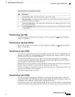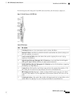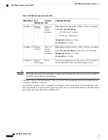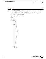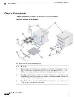
Table 17: XGLC Callouts
Description
Item
Card Ejector Levers
—
Use to insert/remove card to/from chassis.
1
Interlock Switch
—
In its Down position the interlock switch notifies system to safely power down
the card prior to its removal.
2
Card Level Status LEDs
—
Show the status of the card. See
Applying Power and Verifying
Installation
for definitions.
3
Gigabit Ethernet Interface(s)
—
10
Gigabit Ethernet (GE) SFP+ modules. 10Base-SR and 10Base-LR
interfaces are supported, depending on the SFP+ module installed.
4
Optical Line Card (OLC2)
The OLC2 is labeled OLC2 OC-3/STM-1 Multi Mode (or Single Mode depending on SFP type). The OLC2
supports either OC-3 or STM-1 signaling and ATM.
The OLC2 support both SDH and SONET. The basic unit of framing in SDH is STM-1 (Synchronous Transport
Module level - 1), which operates at 155.52 Mbps. SONET refers to this basic unit as STS-3c (Synchronous
Transport Signal - 3, concatenated), but its high-level functionality, frame size, and bit-rate are the same as
STM-1.
SONET offers an additional basic unit of transmission, STS-1 (Synchronous Transport Signal - 1), operating
at 51.84 Mbps
—
exactly one third of an STM-1/STS-3c. The OLC2 concatenates three STS-1 (OC-1) frames
to provide transmission speeds up to 155.52 Mbps with payload rates of 149.76 Mbps and overhead rates of
5.76 Mbps.
The OLC2 optical fiber line card supports network connectivity through Iu or IuPS interfaces to the UMTS
Terrestrial Radio Access Network (UTRAN). These interfaces are commonly used with our SGSN products
to provide either non-IP 3G traffic or all IP 3G traffic (for all-IP packet-based networking) over ATM
(Asynchronous Transfer Mode).
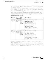
Each OLC2 provides four physical interfaces (ports) that are populated by Small Form-factor Pluggable (SFP)
modules which include LC-type connectors. The Optical (ATM) line card supports two types of SFP modules
(ports) and applicable cabling, but each card supports only one type at-a-time, as indicated in the following
table.
ASR 5000 Installation Guide
32
ASR 5000 Hardware Platform Overview
Optical Line Card (OLC2)
Содержание ASR 5000
Страница 16: ...ASR 5000 Installation Guide xvi About this Guide Contacting Customer Support ...
Страница 64: ...ASR 5000 Installation Guide 48 Installation Procedure Overview Laser Notice ...
Страница 100: ...ASR 5000 Installation Guide 84 Line Card Installation Installing the XGLC ...
Страница 118: ...ASR 5000 Installation Guide 102 Cabling the Switch Processor Input Output Line Card Central Office Alarm Wiring Example ...
Страница 122: ...ASR 5000 Installation Guide 106 Cabling the Fast Ethernet 10 100 Line Card FLC2 Interfaces ...
Страница 136: ...ASR 5000 Installation Guide 120 Cabling the Optical ATM Line Cards Cabling the Optical SFP Interface ...
Страница 140: ...ASR 5000 Installation Guide 124 Cabling the Channelized Line Cards Cabling the Optical SFP Interface ...
Страница 144: ...Figure 49 PFU Wiring Diagram ASR 5000 Installation Guide 128 Cabling the Power Filter Units Power Cable Requirements ...
Страница 148: ...ASR 5000 Installation Guide 132 Cabling the Power Filter Units Connecting the PFU to the Power Source ...
Страница 206: ...ASR 5000 Installation Guide 190 Removing and Installing SMC PC Cards Removing PC Cards ...
Страница 212: ...ASR 5000 Installation Guide 196 Replacing the Chassis Air Filter Installing the Air Filter ...
Страница 220: ...ASR 5000 Installation Guide 204 Replacing a Power Filter Unit What to do with the Failed PFU ...
Страница 266: ...ASR 5000 Installation Guide 250 Safety Electrical and EMC Certifications Korean EMC ...
Страница 270: ...ASR 5000 Installation Guide 254 Environmental Specifications Chassis Air Flow ...
Страница 280: ...ASR 5000 Installation Guide 264 Preparing a Full Height Line Card Slot Remove the Half Height Card Guide ...
Страница 294: ...ASR 5000 Installation Guide 278 Spare Component Recommendations Spare Component Recommendations ...


