2
An SPIO may be equipped with one type of BITS connector
–
BNC or 3-pin.
3
A Small Form-factor Pluggable transceiver is supplied with the GLC2 based on the customer-specified
interface type.
4
Four Small Form-factor Pluggable transceivers are supplied with the QGLC based on the customer-specified
interface type.
5
An enhanced SFP (SFP+) transceiver is supplied with the XGLC based on the customer-specified interface
type.
SPIO Card Interfaces
Each interface on the SPIO card is described below. In each accompanying figure, the interface is shown in
the same orientation as the way it appears on the card.
Console Port
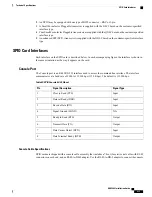
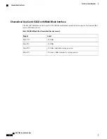
The Console port is an RJ-45 RS-232 interface used to access the command line interface. The interface
communicates at a baud rate of 9600 to 115,200 bps (115.2 Kbps). The default is 115,200 bps.
Table 89: SPIO Console RJ-45 Pinout
Signal Type
Signal Description
Pin
Input
Clear to Send (CTS)
1
Input
Data set Ready (DSR)
2
Input
Receive Data (RX)
3
N/A
Signal Ground (SGND)
4
Output
Ready to Send (RTS)
5
Output
Transmit Data (TX)
6
Input
Data Carrier Detect (DCD)
7
Output
Data Terminal Ready (DTR)
8
Console Cable Specifications
SPIO cards are shipped with a console cable assembly that includes a 7-foot (2 meter) serial cable with RJ-45
connectors on each end, and an RJ-45-to-DB-9 adapter. Use the RJ-45-to-DB-9 adapter to connect the console
ASR 5000 Installation Guide
235
Technical Specifications
SPIO Card Interfaces
Содержание ASR 5000
Страница 16: ...ASR 5000 Installation Guide xvi About this Guide Contacting Customer Support ...
Страница 64: ...ASR 5000 Installation Guide 48 Installation Procedure Overview Laser Notice ...
Страница 100: ...ASR 5000 Installation Guide 84 Line Card Installation Installing the XGLC ...
Страница 118: ...ASR 5000 Installation Guide 102 Cabling the Switch Processor Input Output Line Card Central Office Alarm Wiring Example ...
Страница 122: ...ASR 5000 Installation Guide 106 Cabling the Fast Ethernet 10 100 Line Card FLC2 Interfaces ...
Страница 136: ...ASR 5000 Installation Guide 120 Cabling the Optical ATM Line Cards Cabling the Optical SFP Interface ...
Страница 140: ...ASR 5000 Installation Guide 124 Cabling the Channelized Line Cards Cabling the Optical SFP Interface ...
Страница 144: ...Figure 49 PFU Wiring Diagram ASR 5000 Installation Guide 128 Cabling the Power Filter Units Power Cable Requirements ...
Страница 148: ...ASR 5000 Installation Guide 132 Cabling the Power Filter Units Connecting the PFU to the Power Source ...
Страница 206: ...ASR 5000 Installation Guide 190 Removing and Installing SMC PC Cards Removing PC Cards ...
Страница 212: ...ASR 5000 Installation Guide 196 Replacing the Chassis Air Filter Installing the Air Filter ...
Страница 220: ...ASR 5000 Installation Guide 204 Replacing a Power Filter Unit What to do with the Failed PFU ...
Страница 266: ...ASR 5000 Installation Guide 250 Safety Electrical and EMC Certifications Korean EMC ...
Страница 270: ...ASR 5000 Installation Guide 254 Environmental Specifications Chassis Air Flow ...
Страница 280: ...ASR 5000 Installation Guide 264 Preparing a Full Height Line Card Slot Remove the Half Height Card Guide ...
Страница 294: ...ASR 5000 Installation Guide 278 Spare Component Recommendations Spare Component Recommendations ...


