Verify that the power source from the fuse panel is OFF before attaching power cables to the PFU(s) installed
in the chassis.
Spannungsversorgung abschalten vor Anschluss der Kabel an die Netzteile, um einen elektrischen Schlag zu
vermeiden.
Step 1
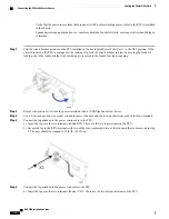
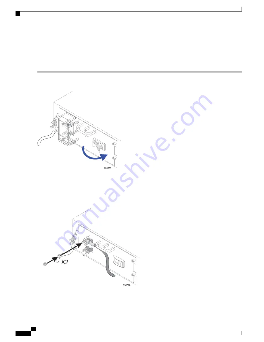
Flip the circuit breaker actuator on the PFU installed in the bay labeled Power Filter Unit 1 to the OFF position. If the
circuit breaker on the PFU is equipped with a locking clip, lock the circuit breaker in place by moving the breaker's
locking clip to the right until the clip's inside tang is recessed in the breaker's actuator opening.
Step 2
Remove the plastic cover from the power terminals with a #2 Phillips head screw driver.
Step 3
Use a 9/16-inch nut driver or socket wrench to remove the nuts and the lock-washers from each of the four terminals.
Step 4
Connect the lug attached to the power return cable to the PFU:
a) Insert the lug over the two terminals labeled RTN. These are the two top terminals on the PFU.
b) Secure the lug to the RTN terminals with two of the four washers and two of the four nuts that you removed in step
3. The nuts should be torqued to 50 in-lb. (5.65 N-m).
Step 5
Connect the lug attached to the power feed cable to the PFU:
a) Insert the lug over the two terminals labeled -VDC. These are the two bottom terminals on the PFU.
ASR 5000 Installation Guide
130
Cabling the Power Filter Units
Connecting the PFU to the Power Source
Содержание ASR 5000
Страница 16: ...ASR 5000 Installation Guide xvi About this Guide Contacting Customer Support ...
Страница 64: ...ASR 5000 Installation Guide 48 Installation Procedure Overview Laser Notice ...
Страница 100: ...ASR 5000 Installation Guide 84 Line Card Installation Installing the XGLC ...
Страница 118: ...ASR 5000 Installation Guide 102 Cabling the Switch Processor Input Output Line Card Central Office Alarm Wiring Example ...
Страница 122: ...ASR 5000 Installation Guide 106 Cabling the Fast Ethernet 10 100 Line Card FLC2 Interfaces ...
Страница 136: ...ASR 5000 Installation Guide 120 Cabling the Optical ATM Line Cards Cabling the Optical SFP Interface ...
Страница 140: ...ASR 5000 Installation Guide 124 Cabling the Channelized Line Cards Cabling the Optical SFP Interface ...
Страница 144: ...Figure 49 PFU Wiring Diagram ASR 5000 Installation Guide 128 Cabling the Power Filter Units Power Cable Requirements ...
Страница 148: ...ASR 5000 Installation Guide 132 Cabling the Power Filter Units Connecting the PFU to the Power Source ...
Страница 206: ...ASR 5000 Installation Guide 190 Removing and Installing SMC PC Cards Removing PC Cards ...
Страница 212: ...ASR 5000 Installation Guide 196 Replacing the Chassis Air Filter Installing the Air Filter ...
Страница 220: ...ASR 5000 Installation Guide 204 Replacing a Power Filter Unit What to do with the Failed PFU ...
Страница 266: ...ASR 5000 Installation Guide 250 Safety Electrical and EMC Certifications Korean EMC ...
Страница 270: ...ASR 5000 Installation Guide 254 Environmental Specifications Chassis Air Flow ...
Страница 280: ...ASR 5000 Installation Guide 264 Preparing a Full Height Line Card Slot Remove the Half Height Card Guide ...
Страница 294: ...ASR 5000 Installation Guide 278 Spare Component Recommendations Spare Component Recommendations ...

