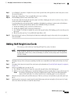
To reduce the risk of electric shock and to ensure proper ventilation, blanking panels must be used to cover any chassis
slot that is not occupied by an application card.
Leere Steckplaetze muessen mit der dafuer vorgesehenen Abdeckplatte geschlossen werden, um die Luftzirkulation
innerhalb des Geraets zu gewaehrleisten und um einen elektrischen Schlag zu vermeiden.
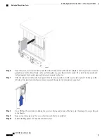
a) Position the blanking panel over the unused chassis slot(s).
b) Use a Phillips #2 screwdriver to tighten the screws at the top and bottom of the blanking panel to secure the panel to
the chassis.
Step 11
Refer to one of the following chapters in this guide for information on cabling the line cards you just installed.
Chapter
Line Card
Cabling the Switch Processor Input/Output Line Card
Switch Processor Input/Output (SPIO)
Cabling the Ethernet 10/100 Line Card
Fast Ethernet Line Card (FLC2)
Cabling the Gigabit Ethernet Line Cards
Gigabit Ethernet Line Card (GLC2)
Quad Gigabit Ethernet Line Card (QGLC)
10 Gigabit Ethernet Line Card (XGLC)
Cabling the Optical (ATM) Line Card
Optical (ATM) (OLC2)
Cabling the Channelized Line Card
Channelized Line Card Interfaces (CLC2)
Adding a 10 Gigabit Ethernet Line Card
The 10 Gigabit Ethernet Line Card (XGLC) is a full-height line card that occupies two half-height slots in
the rear of the ASR 5000 chassis. It accepts a single Small Form-factor Pl (SFP+) transceiver module
for network connectivity.
There are two versions of the XGLC:
•
XGLC SR:
Accepts a 10GBase-SR module for a fiber optical cable with a center wavelength of 850nm
terminated by an LC connector. It can drive an optical signal up to 300 meters using 50/125um fiber
(MMF), and up to 33 meters using 62.5/125um fiber (MMF).
•
XGLC LR:
Accepts a 10GBase-LR module for a fiber optical cable with a center wavelength of 1310nm
terminated by an LC connector. It can drive an optical signal up to 10 kilometers using 50/125um fiber
(SMF).
Install XGLCs behind packet processing cards. You can install a maximum of twelve XGLCs in the chassis.
ASR 5000 Installation Guide
181
Adding Application and Line Cards to an Existing Installation
Adding a 10 Gigabit Ethernet Line Card
Содержание ASR 5000
Страница 16: ...ASR 5000 Installation Guide xvi About this Guide Contacting Customer Support ...
Страница 64: ...ASR 5000 Installation Guide 48 Installation Procedure Overview Laser Notice ...
Страница 100: ...ASR 5000 Installation Guide 84 Line Card Installation Installing the XGLC ...
Страница 118: ...ASR 5000 Installation Guide 102 Cabling the Switch Processor Input Output Line Card Central Office Alarm Wiring Example ...
Страница 122: ...ASR 5000 Installation Guide 106 Cabling the Fast Ethernet 10 100 Line Card FLC2 Interfaces ...
Страница 136: ...ASR 5000 Installation Guide 120 Cabling the Optical ATM Line Cards Cabling the Optical SFP Interface ...
Страница 140: ...ASR 5000 Installation Guide 124 Cabling the Channelized Line Cards Cabling the Optical SFP Interface ...
Страница 144: ...Figure 49 PFU Wiring Diagram ASR 5000 Installation Guide 128 Cabling the Power Filter Units Power Cable Requirements ...
Страница 148: ...ASR 5000 Installation Guide 132 Cabling the Power Filter Units Connecting the PFU to the Power Source ...
Страница 206: ...ASR 5000 Installation Guide 190 Removing and Installing SMC PC Cards Removing PC Cards ...
Страница 212: ...ASR 5000 Installation Guide 196 Replacing the Chassis Air Filter Installing the Air Filter ...
Страница 220: ...ASR 5000 Installation Guide 204 Replacing a Power Filter Unit What to do with the Failed PFU ...
Страница 266: ...ASR 5000 Installation Guide 250 Safety Electrical and EMC Certifications Korean EMC ...
Страница 270: ...ASR 5000 Installation Guide 254 Environmental Specifications Chassis Air Flow ...
Страница 280: ...ASR 5000 Installation Guide 264 Preparing a Full Height Line Card Slot Remove the Half Height Card Guide ...
Страница 294: ...ASR 5000 Installation Guide 278 Spare Component Recommendations Spare Component Recommendations ...

