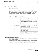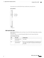
RCC Standby LED States
The Standby LED on the RCC indicates that software is loaded on the card. The card is ready to provide a
path for data or signalling traffic from a line card to a redundant packet processing card. This LED is on during
normal operation for both installed RCCs.
If the LED is not green, use the troubleshooting information in the table to diagnose the problem.
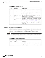
Table 79: RCC Standby LED States
Troubleshooting
Description
Color
This is the normal operating mode.
Card is in standby mode
Green
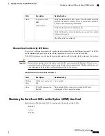
Verify that the Run/Fail LED is green. If so, the card is receiving
power and POST test results are positive. If it is off, refer to
Run/Fail LED States, on page 165
for troubleshooting information.
Card is not receiving
power
OR
Card in Active Mode
None
Check the state of the Active LED. If it is green, the card is in
active mode and the RCC is actively routing traffic from a line
card installed behind a packet processing card that has failed. See
Checking the LEDs on Packet Processing Cards, on page 144
to
determine which packet processing card has failed.
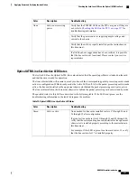
Completing Initial System Configuration
After power is applied to the chassis and the ASR 5000 has successfully booted, the command line interface
(CLI) appears on a terminal connected to the Console port of the SPIO.
The initial configuration requires completing the following tasks via the CLI:
•
Configuring the system for remote access
•
Configuring the management interface with a second IP Address (optional)
•
Configuring system timing
•
Enabling CLI timestamping
•
Configuring system administrative users
•
Configuring for system administrative users (optional)
•
Configuring a chassis key
•
Configuring virtual MAC addresses
•
Configuring packet processing and line card availability
•
Configuring line card and SPIO port redundancy
•
Configuring ASR 5000 link aggregation (optional)
•
Configuring ORBEM and the Web Element Manager (optional)
ASR 5000 Installation Guide
167
Applying Power and Verifying the Installation
Completing Initial System Configuration
Содержание ASR 5000
Страница 16: ...ASR 5000 Installation Guide xvi About this Guide Contacting Customer Support ...
Страница 64: ...ASR 5000 Installation Guide 48 Installation Procedure Overview Laser Notice ...
Страница 100: ...ASR 5000 Installation Guide 84 Line Card Installation Installing the XGLC ...
Страница 118: ...ASR 5000 Installation Guide 102 Cabling the Switch Processor Input Output Line Card Central Office Alarm Wiring Example ...
Страница 122: ...ASR 5000 Installation Guide 106 Cabling the Fast Ethernet 10 100 Line Card FLC2 Interfaces ...
Страница 136: ...ASR 5000 Installation Guide 120 Cabling the Optical ATM Line Cards Cabling the Optical SFP Interface ...
Страница 140: ...ASR 5000 Installation Guide 124 Cabling the Channelized Line Cards Cabling the Optical SFP Interface ...
Страница 144: ...Figure 49 PFU Wiring Diagram ASR 5000 Installation Guide 128 Cabling the Power Filter Units Power Cable Requirements ...
Страница 148: ...ASR 5000 Installation Guide 132 Cabling the Power Filter Units Connecting the PFU to the Power Source ...
Страница 206: ...ASR 5000 Installation Guide 190 Removing and Installing SMC PC Cards Removing PC Cards ...
Страница 212: ...ASR 5000 Installation Guide 196 Replacing the Chassis Air Filter Installing the Air Filter ...
Страница 220: ...ASR 5000 Installation Guide 204 Replacing a Power Filter Unit What to do with the Failed PFU ...
Страница 266: ...ASR 5000 Installation Guide 250 Safety Electrical and EMC Certifications Korean EMC ...
Страница 270: ...ASR 5000 Installation Guide 254 Environmental Specifications Chassis Air Flow ...
Страница 280: ...ASR 5000 Installation Guide 264 Preparing a Full Height Line Card Slot Remove the Half Height Card Guide ...
Страница 294: ...ASR 5000 Installation Guide 278 Spare Component Recommendations Spare Component Recommendations ...

