


3 Introduction to Use
3.5 Data Analysis
71
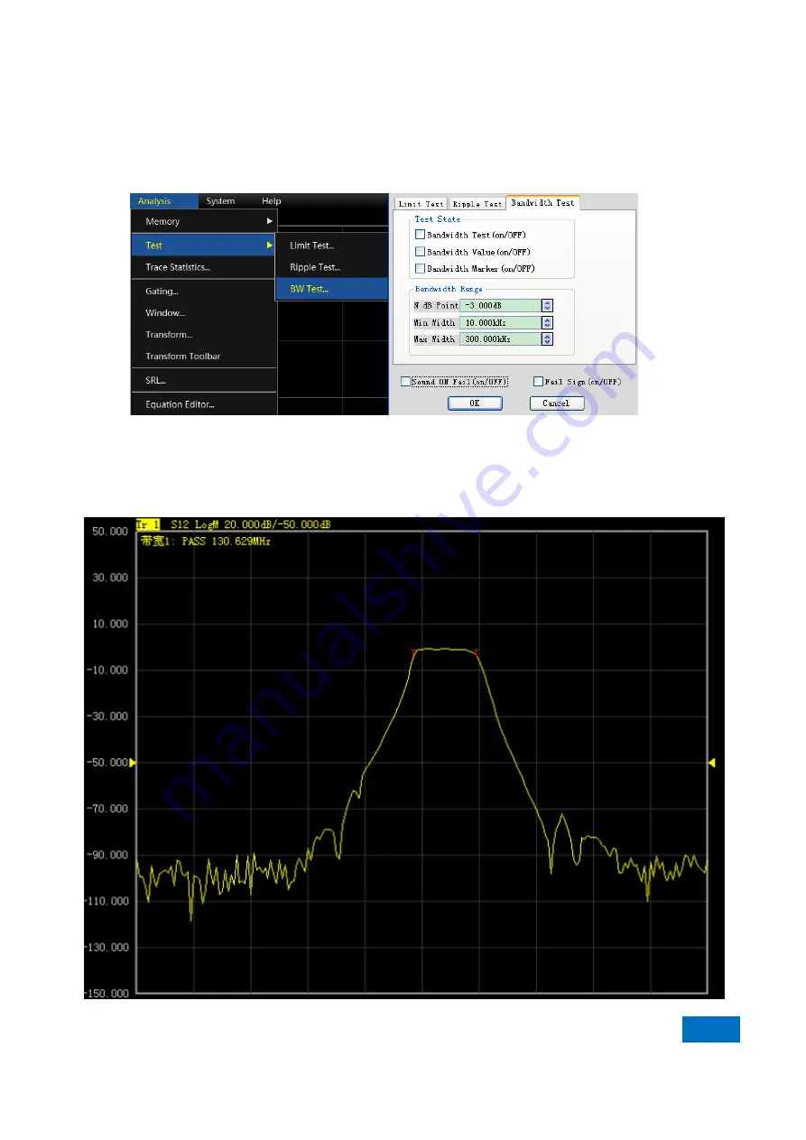
failure of the bandwidth test.
9) Tick the
[Fail Sign on/OFF]
check box in the dialog box. The
FAIL
prompt will be provided in case of failure
of the bandwidth test.
10) Click
[OK]
. Thus the bandwidth test setting is completed.
Fig. 3.65 Dialog Box of Bandwidth Test
3.5.5.2 Display of Bandwidth Test Results
Bandwidth test results will be displayed in the upper left corner of the trace. If the test results are acceptable,
“
PASS
” will be displayed. The red
T
-type bandwidth marks will appear on both sides of the bandwidth.
Содержание AV3672 Series
Страница 1: ...AV3672 Series Vector Network Analyzer User Manual China Electronics Technology Instruments Co Ltd...
Страница 3: ......
Страница 4: ...AV3672 Series Vector Network Analyzer Contents...
Страница 5: ......
Страница 124: ...5 Menu 5 1 Menu structure 120 5 1 2 Track Fig 5 2 Track Menu...
Страница 125: ...5 Menu 5 1 Menu structure 121 5 1 3 Channel Fig 5 3 Channel Menu...
Страница 126: ...5 Menu 5 1 Menu structure 122 5 1 4 Excitation Fig 5 4 Excitation Menu I...
Страница 127: ...5 Menu 5 1 Menu structure 123 Fig 5 5 Excitation Menu II...
Страница 128: ...5 Menu 5 1 Menu structure 124 Fig 5 6 Excitation Menu III...
Страница 129: ...5 Menu 5 1 Menu structure 125 5 1 5 Response Fig 5 7 Response Menu I...
Страница 130: ...5 Menu 5 1 Menu structure 126 Fig 5 8 Repsonse Menu II...
Страница 131: ...5 Menu 5 1 Menu structure 127 Fig 5 9 Response Menu III...
Страница 132: ...5 Menu 5 1 Menu structure 128 Fig 5 10 Response Menu V Fig 5 11 Response IV...
Страница 133: ...5 Menu 5 1 Menu structure 129 5 1 6 Calibration Fig 5 12 Calibration Menu...
Страница 134: ...5 Menu 5 1 Menu structure 130 5 1 7 Marker Fig 5 13 Cursor Menu I...
Страница 135: ...5 Menu 5 1 Menu structure 131 Fig 5 13 Cursor Menu II...
Страница 136: ...5 Menu 5 1 Menu structure 132 Fig 5 15Marker Menu III...
Страница 137: ...5 Menu 5 1 Menu structure 133 5 1 8 Analysis Fig 5 16 Analysis Menu I...
Страница 138: ...5 Menu 5 1 Menu structure 134 Fig 5 17 Analysis Menu II...
Страница 139: ...5 Menu 5 1 Menu structure 135 Fig 5 18 Analysis Menu III...
Страница 140: ...5 Menu 5 1 Menu structure 136 5 1 9 System Fig 5 19 System Menu I...
Страница 141: ...5 Menu 5 1 Menu structure 137 Fig 5 20 System Menu I...
Страница 254: ...8 Basis of Network Measurement 8 3 Amplifier Parameter Specifications 250...
Страница 257: ...8 Basis of Network Measurement 8 4 Complex Impedance 253...
Страница 366: ...Appendix Appendix 3 Frequency Offset Measurement 362 Fig 3 13 Test of Return Loss of Mixer LO Port...
Страница 373: ...Appendix Appendix 4 Pulse Measurement 369 Fig 4 9 Receiver gain configuration Dialog Box...


