9-16
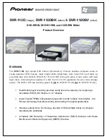
Note that setting Frequency Ref. for Accel/decel (H70) is set to Max Freq and target
freq is set below Max freq. the shape of S-curve may be distorted.
Accel time for S-curve setting
2
18
2
17
H
ACC
H
ACC
ACC
u
u
Decel time for S-curve setting
2
18
2
17
H
dEC
H
dEC
dEC
u
u
ACC, dEC indicate the set time in Drive group.
z
Accel/Decel Disable
Group
Code
Parameter Name
Setting
Range
Initial
Unit
I/O group
I17
[Multi-function input terminal
P1 define]
-
0
~
~
I24
[Multi-function input
terminal P8 define]
24
0 ~24
7
Select one terminal among Multi-function input terminals 1-8 to define Accel/Decel disable.
If P8 is selected, set I24 to 24 to activate this function.
mU
w_
vG
ჹ
Note: If Target
Frequency is below Max
Frequency, the waveform
will be shown with the top
portion cut out.
Freq
H17
H17
H18
H18
Accel/decel
Ref Freq
Target Freq
Содержание Titan CI-001-GS2
Страница 1: ...D GS S Compact Space Ve VFD Frequency and 5 5 5 5 8...
Страница 13: ...1 4 Notes...
Страница 16: ...2 3 2 2 Dimensions CI 002 GS2 4 CI 001 GS2 4...
Страница 17: ...2 4 CI 003 GS2 4 CI 005 GS2 4 CI 007 GS2 4 CI 010 GS2 4 H W D W1 A A H1 W1 B B...
Страница 19: ......
Страница 25: ...3 6 5 5 7 5 kW 5 5 mm2 M4 3 5 mm2 M4...
Страница 45: ...6 4 Notes...
Страница 68: ...CHAPTER 8 CONTROL BLOCK DIAGRAM m G k G h Vk Vm w t t...
Страница 71: ...8 4 Notes...
Страница 119: ...10 26 Notes...
Страница 141: ...12 10 Ex 2 100 2 _ _ 1 _ _ _ 76 u steady T acc T steady T dec T dec T H m U X Y...
Страница 159: ...13 18 Notes...
Страница 169: ...15 4...
Страница 170: ...15 5 Notes...
Страница 171: ......