Chapter 2
2-3
2.2 Basic Sequence
2.2.1 Basic Sequence of Operation
0019-5072
imageCLASS MF9170c / imageCLASS MF9150c / imageCLASS MF8450c
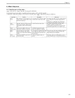
The operational sequence of a printer is controlled by the microcomputer (CPU) on the DC controller.
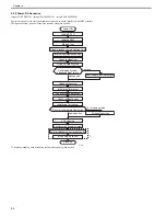
The purposes of each period, from power-ON until the inverter motor stops after the completion of printing, are listed below.
T-2-1
Operation
Interval
Description
Remarks
WAIT
(Wait)
From either power switch is turned ON or
front cover is closed until each drum phase
adjustment is completed.
To clear drum surface potential, to adjust
each drum phase, and to clean the ETB.
The machine detects the toner level, cartridge presence,
new cartridge, and environmental status during the
period.
It also executes the calibration (color displacement
correction and image stability control) as required.
STBY
(Stand-by)
From end of WAIT or LSTR period until
either the print command is input from the
main controller or power switch is turned
OFF.
To keep the machine ready to print.
The machine goes into sleep mode when a sleep
command is sent from the main controller.
It executes the color displacement correction and the
image stability control when each command is sent.
INTR
(Initial rotation)
From the print command is input by the
main controller until paper is picked up.
To stabilize the photosensitive drum
sensitivity in preparation for printing.
PRINT
(Print)
From /TOP signal is sent to the main
controller after INTR period until the
fixing delivery sensor detects trailing edge
of paper.
To form image on the photosensitive drum
based on the video signals sent from the
main controller and to transfer the toner
image onto paper.
The printer executes the image stabilization control in
every specified number of prints or specified time
elapsed after the power is turned ON.
LSTR
(Last rotation)
From the end of PRINT period until the
inverter motor stops.
To deliver the last paper out of the
machine.
The machine returns to the INTR period as soon as
another print command is sent from the main controller.
Содержание imageCLASS MF8450c
Страница 16: ...Chapter 1 Introduction ...
Страница 55: ...Chapter 2 Basic Operation ...
Страница 61: ...Chapter 3 Main Controller ...
Страница 75: ...Chapter 4 Original Exposure System ...
Страница 88: ...Chapter 5 Original Feeding System ...
Страница 105: ...Chapter 6 Laser Exposure ...
Страница 113: ...Chapter 7 Image Formation ...
Страница 150: ...Chapter 8 Pickup and Feed System ...
Страница 184: ...Chapter 9 Fixing System ...
Страница 200: ...Chapter 10 External and Controls ...
Страница 230: ...Chapter 11 Maintenance and Inspection ...
Страница 233: ...Chapter 12 Measurement and Adjustments ...
Страница 237: ...Chapter 13 Correcting Faulty Images ...
Страница 251: ...Chapter 13 13 13 13 3 5 PCBs 13 3 5 1 PCBs 0019 5065 imageCLASS MF9170c imageCLASS MF9150c imageCLASS MF8450c ...
Страница 256: ...Chapter 13 13 18 F 13 19 21 22 28 29 30 31 24 14 15 16 23 26 25 32 27 20 19 18 17 2 13 6 10 33 1 8 4 3 12 11 5 7 9 ...
Страница 260: ...Chapter 14 Error Code ...
Страница 272: ...Chapter 15 Special Management Mode ...
Страница 280: ...Chapter 16 Service Mode ...
Страница 322: ...Chapter 17 Upgrading ...
Страница 327: ...Chapter 17 17 4 3 Click Next F 17 4 4 Select a USB connected device and click Next F 17 5 ...
Страница 328: ...Chapter 17 17 5 5 Click Start F 17 6 6 Click Yes F 17 7 Download will be started F 17 8 ...
Страница 330: ...Chapter 18 Service Tools ...
Страница 334: ...Appendix ...
Страница 349: ......

