Chapter 6
6-1
6.1 Overview/Configuration
6.1.1 Overview
0019-5006
imageCLASS MF9170c / imageCLASS MF9150c / imageCLASS MF8450c
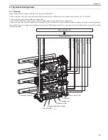
The laser exposure system forms latent images on the photosensitive drum according to the video signals with the control by the DC controller.
The laser exposure system consists of the laser scanner unit.
The 2 laser driver PCBs, the 2 scanner motors, and the 2 polygon mirrors are installed on the laser scanner unit.
There are two (two colors of) laser diodes for one laser driver PCB. The laser beams of two colors emitted from the laser diode are reflected by one polygon mirror.
In this machine, the process speed varies according to the print mode. The rotational speed of the scanner motor and the laser light intensity are switched according
to the process speed.
F-6-1
/SCNM1ACC, /SCNM1DEC
/SCNM2ACC, /SCNM2DEC
LDCTRL, VIDEO
LDCTRL, VIDEO
/BD3I
/BD1I
LD1PDOUT, LD2PDOUT
LD3PDOUT, LD4PDOUT
LDPWRH
LDPWRH
Photosensitive drum
Polygon mirror (Four-faced)
Reflective mirror
Focusing lens
Laser driver PCB
DC controller PCB
Main controller PCB
Scanner motor
BD sensor
Содержание imageCLASS MF8450c
Страница 16: ...Chapter 1 Introduction ...
Страница 55: ...Chapter 2 Basic Operation ...
Страница 61: ...Chapter 3 Main Controller ...
Страница 75: ...Chapter 4 Original Exposure System ...
Страница 88: ...Chapter 5 Original Feeding System ...
Страница 105: ...Chapter 6 Laser Exposure ...
Страница 113: ...Chapter 7 Image Formation ...
Страница 150: ...Chapter 8 Pickup and Feed System ...
Страница 184: ...Chapter 9 Fixing System ...
Страница 200: ...Chapter 10 External and Controls ...
Страница 230: ...Chapter 11 Maintenance and Inspection ...
Страница 233: ...Chapter 12 Measurement and Adjustments ...
Страница 237: ...Chapter 13 Correcting Faulty Images ...
Страница 251: ...Chapter 13 13 13 13 3 5 PCBs 13 3 5 1 PCBs 0019 5065 imageCLASS MF9170c imageCLASS MF9150c imageCLASS MF8450c ...
Страница 256: ...Chapter 13 13 18 F 13 19 21 22 28 29 30 31 24 14 15 16 23 26 25 32 27 20 19 18 17 2 13 6 10 33 1 8 4 3 12 11 5 7 9 ...
Страница 260: ...Chapter 14 Error Code ...
Страница 272: ...Chapter 15 Special Management Mode ...
Страница 280: ...Chapter 16 Service Mode ...
Страница 322: ...Chapter 17 Upgrading ...
Страница 327: ...Chapter 17 17 4 3 Click Next F 17 4 4 Select a USB connected device and click Next F 17 5 ...
Страница 328: ...Chapter 17 17 5 5 Click Start F 17 6 6 Click Yes F 17 7 Download will be started F 17 8 ...
Страница 330: ...Chapter 18 Service Tools ...
Страница 334: ...Appendix ...
Страница 349: ......

