RIVER IDROTECH 18 - 24 - 24H2O
23
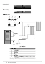
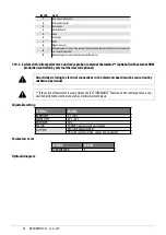
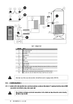
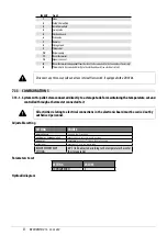
LEGEND
1
Anti-condensation valve
2
External thermostat
3
Room probe
4
Electronic board
5
Stove
6
Zone valve
7
DHW
8
Expansion vessel
A
Wiring diagram for connecting external thermostat and zone valve (in the case of several val-
ves, connect in parallel)
B
Wiring diagram for connecting the external thermostat
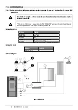
7.10.2 System with: direct pellet stove and room probe or external thermostat** (optional) with external DHW
production controlled by external thermostat (optional)
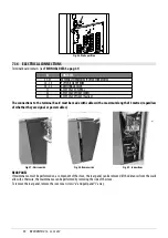
All activities relating to electrical connections in the electronic board must be carried out by
authorised personnel.
** If the external thermostat is used, activate the “EXT THERMOSTAT” function on the control panel and con-
nect it directly to the electronic board (see electrical system below).
Adjustable setting
SETTING
VALUES
ROOM TEMP.
5°C - 35°C
WATER TEMP.
30°C - 80°C
DHW TEMP
75°C
SEASON
WINTER (summer may be activated)
AUTO ECO
OFF (with winter setting)
ON (with summer setting, cannot be deactivated)
Parameters to set
SETTING
VALUES
CONFIGURATION
2
Hydraulic diagram
Содержание RIVER IDROTECH 18
Страница 42: ...RIVERIDROTECH18 24 24H2O 42 10 2 ELECTRONIC BOARD WITH DHW Fig 68 ElectricalboardwithDHW ...
Страница 46: ...NOTE ...
Страница 47: ...NOTE ...


