RIVER IDROTECH 18 - 24 - 24H2O
30
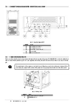
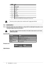
Fig. 46 - Probe position
7.16 ELECTRICAL CONNECTIONS
Terminal board contacts (see
N°
CONTACTS
21 -21
EXTERNAL THERMOSTAT/PUFFER THERMOSTAT
24 - 24
PUFFER/BOILER PROBE
14 - 15
ADDITIONAL BOILER
12
3-WAY VALVE NEUTRAL
33
3-WAY VALVE PHASE (DHW)
34
3-WAY VALVE PHASE (heating)
The connections to the terminal board must be made with cables with a maximum length of 3 metres (regardless
of whether they are signal or power cables).
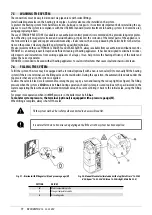
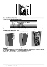
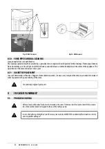
Fig. 47 - Unscrew side
Fig. 48 - Remove side
Fig. 49 - Connections
REAR PANEL
If maintenance must be performed on a component of the stove, the rear panel can be removed (if the distances from the walls
allow it), otherwise, the maintenance can be performed by removing the side of the stove.
To remove the rear panel, remove the seven rear screws “a” and pull panel “L” away.
Содержание RIVER IDROTECH 18
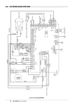
Страница 42: ...RIVERIDROTECH18 24 24H2O 42 10 2 ELECTRONIC BOARD WITH DHW Fig 68 ElectricalboardwithDHW ...
Страница 46: ...NOTE ...
Страница 47: ...NOTE ...


