RIVER IDROTECH 18 - 24 - 24H2O
24
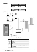
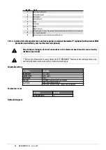
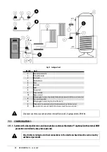
Fig. 41 - Configuration 2
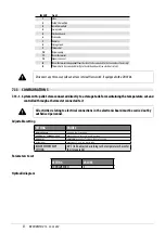
LEGEND
1
Anti-condensation valve
2
External thermostat
3
Room probe
4
Electronic board
5
Stove
6
Zone valve
7
DHW
8
Storage tank
9
Thermostat bulb
10
Expansion vessel
A
Wiring diagram for connecting external thermostat and zone valve (in the case of several val-
ves, connect in parallel)
B
Wiring diagram for connecting the external thermostat
C
Thermostat to be connected directly to the electronic board (see electrical system)
D
3-way valve to be connected directly to the electronic board (see electrical system)
Disconnect any three-way valve and stove internal flow switch, if equipped with a DHW kit.
7.11 CONFIGURATION 3
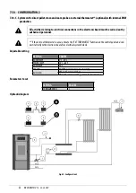
7.11.1 System with: direct pellet stove and room probe or external thermostat** (optional) with external DHW
production controlled by box probe (optional)
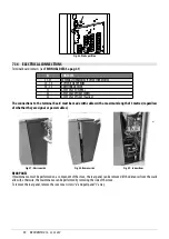
All activities relating to electrical connections in the electronic board must be carried out by
authorised personnel.
Содержание RIVER IDROTECH 18
Страница 42: ...RIVERIDROTECH18 24 24H2O 42 10 2 ELECTRONIC BOARD WITH DHW Fig 68 ElectricalboardwithDHW ...
Страница 46: ...NOTE ...
Страница 47: ...NOTE ...


