RIVER IDROTECH 18 - 24 - 24H2O
29
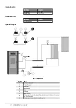
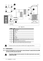
Hydraulic diagram
Fig. 45 - Configuration with storage tank and auxiliary wall-mounted boiler
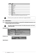
LEGEND
1
Anti-condensation valve
2
Electronic board
3
Storage tank
4
Room thermostat
5
Storage tank thermostat
6
Switch box
7
Strap-on thermostat
8
Booster Pump
9
Non-return valve
10
Expansion vessel
11
Hot H2O manifold
12
Cold H2O manifold
13
Radiator
14
Auxiliary boiler
15
Zone valve
A
Boiler power supply
B
Auxiliary system pump supply
C
Alarm signal
7.15 OPERATING MODE
The operating mode for hydro boilers is AUTOMATIC only (manual mode is not envisioned). Flame modulation is managed accor-
ding to the “System configuration” of the room probe placed on the rear of the appliance (see drawing), by the external thermo-
stat, by the boiler water temperature or by the NTC probes.
Содержание RIVER IDROTECH 18
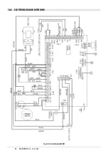
Страница 42: ...RIVERIDROTECH18 24 24H2O 42 10 2 ELECTRONIC BOARD WITH DHW Fig 68 ElectricalboardwithDHW ...
Страница 46: ...NOTE ...
Страница 47: ...NOTE ...


