


2-22
2002 Buell P3: Chassis
HOME
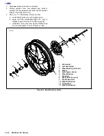
ASSEMBLY
1.
See
Figure 2-31.
Check piston assembly components.
a. Small end of spring (1) sits behind primary cup (2).
Large side of primary cup faces spring.
b.
Secondary cup (3) sits within ridge at middle of pis-
ton (4).
2.
Insert piston assembly, spring first, into master cylinder.
Secure with a
new
snap ring (6).
3.
Install ridge on boot (5) into groove on piston (4).
4.
See
Figure 2-28.
Install front brake hand lever.
a. Align hole in lever (3) with hole in master cylinder
assembly.
b.
Lubricate pivot bolt (2) with LOCTITE ANTI-SEIZE.
c.
Install pivot bolt through top of assembly. Tighten to
4-13
in-lbs
(0.5-1.5 Nm).
d. Install
nut (1) (metric). Tighten to 44-62
in-lbs
(5-
7 Nm).
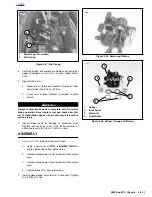
5.
See
Figure 2-27.
Install front brake lamp switch (7).
a. Attach front brake switch with screw, washer and
lockwasher (1). Tighten to 7-13
in-lbs
(0.8-1.5 Nm).
b.
Test switch action. Tang (3) on switch must release
when hand lever (2) is moved.
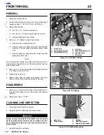
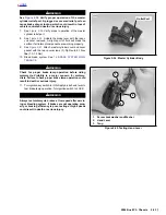
INSTALLATION
1.
See
Figure 2-27.
Fasten master cylinder to handlebar by
installing clamp (2) and screws (1) (metric). Tighten to
80-120
in-lbs
(9-14 Nm).
1
1
WARNING
1
WARNING
Use only new black banjo washers (See Parts Catalog for
Part No.) with D.O.T. 4 brake fluid. Earlier silver banjo
washers are not compatible with D.O.T. 4 fluid and will
not seal properly over time. Failure to comply may
adversely affect braking ability and lead to brake failure
which could result in death or serious injury.
CAUTION
To avoid leakage, ensure that banjo washers, banjo bolt,
hydraulic brake line and master cylinder bore are com-
pletely clean.
2.
Connect brake line (5) to master cylinder using two
new
banjo washers (4) and banjo bolt (6) (metric). Tighten to
16-20 ft-lbs (22-27 Nm).
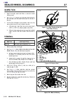
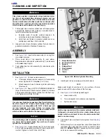
3.
See
Figure 2-32.
Verify brake lamp switches are secure.
Attach wires to switches.
4.
Install mirror parallel to handlebars.
5.
See
Figure 2-27.
Remove the two master cylinder cover
screws (3), cover and cover gasket.
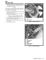
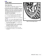
6.
See
Figure 2-33.
With the master cylinder in a level posi-
tion, add
D.O.T. 4 BRAKE FLUID
. Bring fluid level to
within 0.125 in. (3.2 mm) of molded boss inside front
master cylinder reservoir.
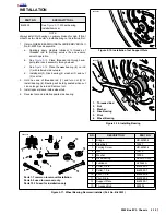
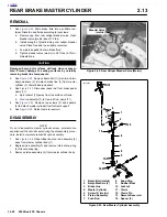
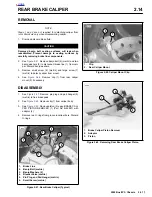
Figure 2-31. Piston Assembly
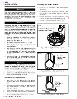
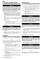
Figure 2-32. Brake Lamp Switch Connectors
Figure 2-33. Brake Fluid Level
6491
1.
Spring
2.
Primary Cup
3.
Secondary Cup
4.
Piston
5.
Boot
6.
Snap Ring
1
2
3
4
6
5
Connectors
6569
Brake Fluid Level
a0214x2x
Содержание 2002 P3
Страница 2: ......
Страница 17: ...A 15 Appendix A Tools HOME ...
Страница 32: ...C 3 Appendix C Metric Conversions HOME ...
Страница 41: ...1 8 2002 Buell P3 Maintenance HOME NOTES ...
Страница 75: ......
Страница 111: ...2 36 2002 Buell P3 Chassis HOME NOTES ...
Страница 143: ...2 68 2002 Buell P3 Chassis HOME NOTES ...
Страница 144: ...2002 Buell P3 Chassis 2 69 HOME ...
Страница 146: ......
Страница 147: ......
Страница 223: ...3 76 2002 Buell P3 Engine HOME NOTES ...
Страница 225: ......
Страница 256: ...2002 Buell P3 Fuel System 4 31 HOME ...
Страница 258: ......
Страница 259: ......
Страница 279: ...5 20 2002 Buell P3 Electric Starter HOME NOTES ...
Страница 281: ......
Страница 327: ......
Страница 398: ...2002 Buell P3 Electrical 7 71 HOME ...
Страница 399: ...SUBJECT PAGE NO A 1 TOOLS A 1 B 1 ELECTRICAL CONNECTORS B 1 C 1 METRIC INFORMATION C 1 Table Of Contents APPENDICES ...
Страница 400: ...Product 1 2 ...