


2002 Buell P3: Chassis
2-65
HOME
HANDLEBARS
2.30
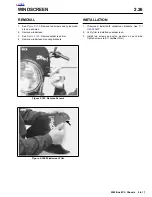
REMOVAL
1.
See
Figure 2-111.
Remove left side switch housing (13).
2.
Loosen clutch adjuster and remove cable (8).
3.
Unplug clutch interlock (9).
4.
Remove hand grip (12)
5.
Loosen lever holder bolt (4) and slide off of handlebar
(3).
6.
Slide rubber boot off the throttle cable adjusters. Loosen
cable adjuster lock on each adjuster.
7.
Remove two screws on front housing. Separate hous-
ings (14) from handlebar.
8.
Remove cables from notches in housings.
9.
Unhook ferrules from cable wheel.
10. Remove throttle grip (15).
11. Remove front master cylinder clamp bolts.
12. Remove master cylinder.
13. Remove handlebar clamp screws (1) and riser caps (2).
14. Remove handlebar (3).
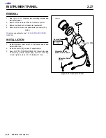
INSTALLATION
1.
Position bar (3) on risers.
2.
Install riser caps (2) and bolts (1).
3.
Tighten bolts in steps maintaining even gap between
riser and cap. Final torque to 10-12 ft-lbs. (14-16 Nm).
4.
Install master cylinder. Tighten master cylinder clamp
bolts to 80-120
in-lbs.
(9-14 Nm).
5.
Install throttle grip.
6.
Hook ferrels to cable wheel. Position cables in notches of
switch housing (14).
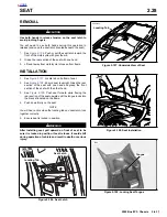
7.
Position housings on right handlebar. Front housing has
locating pin that must align with hole in handlebar. Install
fasteners, longer screw on bottom. Tighten fasteners to
25-33
in-lbs
(3-4 Nm).
8.
Plug in front brake lever switch (16).
9.
Install clutch perch. Torque clutch lever screw (4) to 50-
60 in-lbs (6-7 Nm).
10. Install hand grip (12).
11. Install clutch cable (8).
12. Adjust clutch. See
1.9 CLUTCH.
13. Plug terminal into clutch interlock switch (9).
14. Install left side switch housing (13). Torque fasteners to
25-33
in-lbs
(3-4 Nm).
Figure 2-111. Handlebar Assembly
1.
Handlebar Clamp Screw
2.
Clamp
3.
Handlebars
4.
Clutch Lever Screw
5.
Clutch Lever Bolt
6.
Clutch Lever Handle
7.
Nut
8.
Clutch Cable
9.
Switch
10. O-ring
11. Clamp
12. Left Handlebar Grip
13. Left Switch Assembly
14. Right switch Assembly
15. Throttle
16. Brake Lever Switch
1
14
13
3
2
15
16
4
6
12
9
11
10
8
a0133x2x
5
7
Содержание 2002 P3
Страница 2: ......
Страница 17: ...A 15 Appendix A Tools HOME ...
Страница 32: ...C 3 Appendix C Metric Conversions HOME ...
Страница 41: ...1 8 2002 Buell P3 Maintenance HOME NOTES ...
Страница 75: ......
Страница 111: ...2 36 2002 Buell P3 Chassis HOME NOTES ...
Страница 143: ...2 68 2002 Buell P3 Chassis HOME NOTES ...
Страница 144: ...2002 Buell P3 Chassis 2 69 HOME ...
Страница 146: ......
Страница 147: ......
Страница 223: ...3 76 2002 Buell P3 Engine HOME NOTES ...
Страница 225: ......
Страница 256: ...2002 Buell P3 Fuel System 4 31 HOME ...
Страница 258: ......
Страница 259: ......
Страница 279: ...5 20 2002 Buell P3 Electric Starter HOME NOTES ...
Страница 281: ......
Страница 327: ......
Страница 398: ...2002 Buell P3 Electrical 7 71 HOME ...
Страница 399: ...SUBJECT PAGE NO A 1 TOOLS A 1 B 1 ELECTRICAL CONNECTORS B 1 C 1 METRIC INFORMATION C 1 Table Of Contents APPENDICES ...
Страница 400: ...Product 1 2 ...