


2002 Buell P3: Electrical
7-59
HOME
ELECTRONIC SPEEDOMETER
7.25
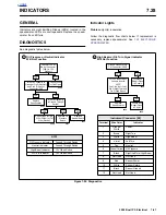
GENERAL
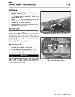
The electronic speedometer consists of a speed sensor,
function switch and the speedometer. The speed sensor is
mounted on the right side of the transmission case, below the
starter. The sensor circuitry is that of a Hall-Effect sensor that
is triggered by the gear teeth of 5th gear on the transmission
main shaft. The output from the sensor is a series of pulses
that are interpreted by speedometer circuitry to control the
position of the speedometer needle and the liquid crystal dis-
play (LCD) odometer display. The odometer mileage is per-
manently stored and will not be lost when electrical power is
turned off or disconnected. The function switch allows switch-
ing, or “toggling” between the odometer and trip odometer
displays. T zero the trip odometer, have the odometer display
visible, press and keep the function switch depressed. The
trip odometer mileage will be displayed for 2 to 3 seconds
and then the mileage will return to 0 miles.
The odometer can display seven numbers to indicate a maxi-
mum of 999999.9 miles. The trip odometer can display five
numbers for a maximum of 9999.9 miles.
Circuitry in the speedometer also conditions the sensor input
to provide an input to the turn signal canceller.
Replace the speedometer if the unit is not working properly.
However, before replacing a component, check that the prob-
lem is not caused by a faulty cable or loose wire connection.
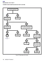
DIAGNOSTICS
Blast Models have a speedometer with self-diagnostic capa-
bilities.
General
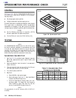
The reset switch is used to change the odometer display
between mileage and trip values and to reset the trip odome-
ter. It is also used to identify the speedometer calibration and
to enter the diagnostic mode, clear diagnostic codes and exit
the diagnostic mode.
Diagnostic Mode
The diagnostic mode is entered by turning the ignition switch
from OFF to ON while holding the reset switch in. The normal
power-up sequence will occur before entering the diagnostic
mode. Diagnostic codes set during this power-up sequence
will be stored as well.
NOTE
Make sure no Diagnostic Codes are indicated before reset is
held in for more than 5 seconds or diagnostic information will
be lost.
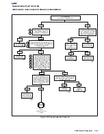
When in the diagnostic mode, the odometer will display the
first diagnostic code. When the trip switch is pressed again,
the next code will be shown. If the trip switch is pressed for
more than 5 seconds at any time while in the diagnostic
mode, the
diagnostic code displayed will be erased
.
There are seven different diagnostic codes available. They
are as follows:
d01
- Speed sensor power output shorted low
d02
- Speed sensor power output shorted high or open
d03
- Not used
d04
- Not used
d05
- Speed sensor return shorted high
d06
- Speed sensor return shorted low
d07
- Not used
d08
- Speedometer power over voltage
d09
- Speed output shorted high
d10
- Speed output shorted low or open
CAL XX
- Speedometer application calibration number:
14 = domestic
When in the diagnostic mode, all codes are displayed in
sequence from d01 to d10.
As a code appears in the display (for instance d02), it will
read “d02SEt” of set or “d02CLr” if clear.
The diagnostic mode is exited either by turning ignition from
ON to OFF to ON again without depressing the reset switch
or if a speed signal greater than 5 m.p.h. is detected.
Diagnostics cannot be performed if a system voltage is less
than 9 VDC or greater than 16 VDC. The only exception is
d08
which is set when the system voltage is greater than 16
VDC.
After all diagnostic codes are displayed, the speedometer
calibration number is displayed (
CAL14
).
Reset Switch Replacement
1.
Remove odometer reset boot from instrument panel.
2.
Unscrew bezel ring from reset switch and pull switch out
from behind instrument panel.
3.
Cut wires from switch.
4.
Install
new
switch wires using SEALED WIRE SPLICES.
5.
Position
new
reset switch in squared boss Behind instru-
ment panel.
6.
Install bezel inside of rubber boot.
7.
Install rubber boot/bezel assembly to odometer reset
switch.
Содержание 2002 P3
Страница 2: ......
Страница 17: ...A 15 Appendix A Tools HOME ...
Страница 32: ...C 3 Appendix C Metric Conversions HOME ...
Страница 41: ...1 8 2002 Buell P3 Maintenance HOME NOTES ...
Страница 75: ......
Страница 111: ...2 36 2002 Buell P3 Chassis HOME NOTES ...
Страница 143: ...2 68 2002 Buell P3 Chassis HOME NOTES ...
Страница 144: ...2002 Buell P3 Chassis 2 69 HOME ...
Страница 146: ......
Страница 147: ......
Страница 223: ...3 76 2002 Buell P3 Engine HOME NOTES ...
Страница 225: ......
Страница 256: ...2002 Buell P3 Fuel System 4 31 HOME ...
Страница 258: ......
Страница 259: ......
Страница 279: ...5 20 2002 Buell P3 Electric Starter HOME NOTES ...
Страница 281: ......
Страница 327: ......
Страница 398: ...2002 Buell P3 Electrical 7 71 HOME ...
Страница 399: ...SUBJECT PAGE NO A 1 TOOLS A 1 B 1 ELECTRICAL CONNECTORS B 1 C 1 METRIC INFORMATION C 1 Table Of Contents APPENDICES ...
Страница 400: ...Product 1 2 ...