


3-38
2002 Buell P3: Engine
HOME
Fitting Cylinder to Piston
Since pistons cannot be accurately measured with standard
measuring instruments, the bore sizes must be measured.
Bore sizes are listed in
Table 3-10.
Example: A 0.005 in.
(0.127 mm) oversize piston will have the proper clearance
with a bore size of 3.502 in. ± 0.0002 in. (88.951 mm ±
0.0051 mm).
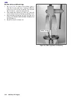
Boring and Honing Cylinder
When cylinder requires oversize reboring to beyond 0.030 in.
(0.762 mm), the oversize limit has been exceeded and cylin-
der must be replaced.
1.
Bore cylinder with gaskets and torque plates attached.
Bore to 0.003 in. (0.076 mm) under the desired finished
size.
2.
Hone the cylinder to its finished size using a 280 grit rigid
hone followed by a 240 grit flexible ball hone. Honing
must be done with the torque plates attached. All honing
must be done from the bottom (crankcase) end of the
cylinder. Work for a 60° crosshatch pattern.
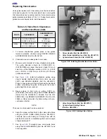
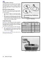
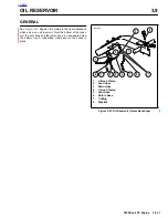
Fitting Piston Rings
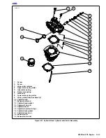
See
Figure 3-71.
Piston rings are of two types: compression
and oil control. The two compression rings are positioned in
the two upper piston ring grooves. The dot on the second
compression ring must face upward. Ring sets are available
to fit standard and oversize pistons.
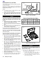
Piston ring sets must be properly fitted to piston and cylinder:
1.
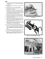
See
3.1 SPECIFICATIONS
. See
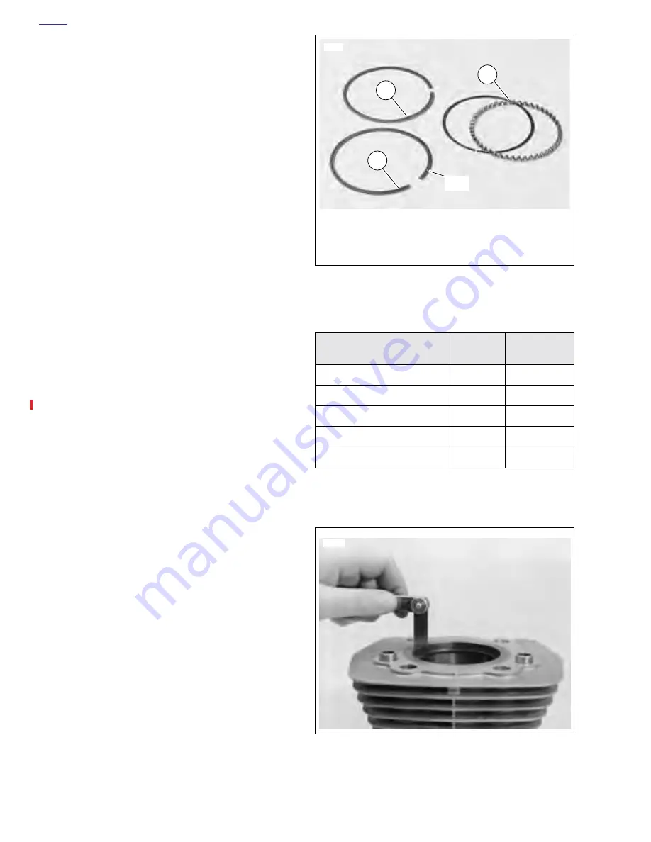
Figure 3-72.
Place pis-
ton in cylinder about 1/2 in. (12.7 mm) from top. Set ring
to be checked squarely against piston as shown. Check
end gap with thickness gauge.
NOTE
See
SERVICE WEAR LIMITS
for end gap dimensions. Do
not file rings to obtain proper gap.
Figure 3-71. Piston Rings
Table 3-10. Final Cylinder Bore Sizes
BORE SIZES
IN.
MM
Standard bore*
3.4978 in.
88.8441 mm
0.005 in. OS bore (0.127 mm)
3.502 in.
88.951 mm
0.010 in. OS bore (0.254 mm)
3.507 in.
89.078 mm
0.020 in. OS bore (0.508 mm)
3.517 in.
89.332 mm
0.030 in. OS bore (0.762 mm)
3.527 in.
89.586 mm
*All bore sizes + 0.0002 in. (0.0051 mm)
Figure 3-72. Measuring Ring End Gap
1.
Top Compression Ring – Install either side up
2.
Second Compression Ring – Install dot toward
top
3.
Oil Control Rings
2
1
3
6612
Dot
2783a
Содержание 2002 P3
Страница 2: ......
Страница 17: ...A 15 Appendix A Tools HOME ...
Страница 32: ...C 3 Appendix C Metric Conversions HOME ...
Страница 41: ...1 8 2002 Buell P3 Maintenance HOME NOTES ...
Страница 75: ......
Страница 111: ...2 36 2002 Buell P3 Chassis HOME NOTES ...
Страница 143: ...2 68 2002 Buell P3 Chassis HOME NOTES ...
Страница 144: ...2002 Buell P3 Chassis 2 69 HOME ...
Страница 146: ......
Страница 147: ......
Страница 223: ...3 76 2002 Buell P3 Engine HOME NOTES ...
Страница 225: ......
Страница 256: ...2002 Buell P3 Fuel System 4 31 HOME ...
Страница 258: ......
Страница 259: ......
Страница 279: ...5 20 2002 Buell P3 Electric Starter HOME NOTES ...
Страница 281: ......
Страница 327: ......
Страница 398: ...2002 Buell P3 Electrical 7 71 HOME ...
Страница 399: ...SUBJECT PAGE NO A 1 TOOLS A 1 B 1 ELECTRICAL CONNECTORS B 1 C 1 METRIC INFORMATION C 1 Table Of Contents APPENDICES ...
Страница 400: ...Product 1 2 ...