2002 Buell P3: Drive/Transmission
6-29
HOME
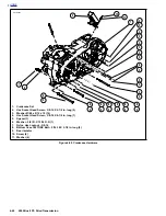
TRANSMISSION ASSEMBLY
6.10
MAINSHAFT SUB-ASSEMBLY
CAUTION
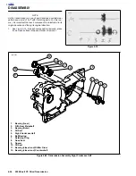
During assembly, the split bearings (8) and the internal
bores of the gears must be lubricated with SPORT-
TRANS FLUID prior to assembly. Leaving these parts dry
could accelerate wear at start-up.
1.
See
Figure 6-42.
Install new retaining ring (11) and
thrust washer (10) onto mainshaft (6) in the first ring
groove from the end.
2.
Install split bearing (8) onto mainshaft.
3.
Locate mainshaft 4th gear (9), which can be identified by
the two radial grooves at one side. Slide gear (9) onto
shaft. Position gear over bearing (8) next to spacer (7).
4.
Place spacer (7) over mainshaft and position next to split
bearing (8).
5.
Slide mainshaft 1st gear (12) onto mainshaft with the
fork groove facing 4th gear (9).
6.
Install thrust washer (10) and new retaining ring (11) next
to mainshaft 1st gear (12).
NOTE
It will be necessary to push the retaining ring into final posi-
tion (ring groove) with a screwdriver.
7.
Install split bearing (8) onto mainshaft.
8.
Install mainshaft 3rd gear (13) onto shaft over bearing
(8).
9.
Install thrust washer (10) and new retaining ring (11).
10. Install mainshaft 2nd gear (14) onto shaft with the fork
groove facing 3rd gear(13).
COUNTERSHAFT SUB-ASSEMBLY
1.
See
Figure 6-42.
Install new retaining ring (11) and thrust
washer (10) onto countershaft (18) in the second ring
groove from the end.
2.
Install split bearing (8) onto countershaft.
3.
Locate countershaft 1st gear (17), which can be identi-
fied by the two radial grooves at one side. Slide gear (17)
onto shaft. Position gear over bearing (8).
4.
Install thrust washer (10) and new retaining ring (11) next
to gear (17).
5.
Locate countershaft 4th gear (16). This flat, shoulderless
gear is splined and has a single radial groove at one
side. Position gear next to retaining ring (11) on counter-
shaft. Place beveled washer (spacer) (15) over end of
shaft with beveled side away from countershaft 4th gear
(16).
6.
Install countershaft 3rd gear (19) on countershaft with
fork groove facing away from countershaft 1st gear (17).
7.
Install new retaining ring (11) on countershaft. Position
new retaining ring in the second ring groove from the
end. Install thrust washer (10) next to retaining ring (11).
Install split bearing (8) in seat next to washer (10).
5.
Install countershaft 2nd gear (20) with the locking dogs
facing countershaft 3rd gear (19).
6.
Install countershaft 5th gear (21) on countershaft.
7.
Install new retaining ring(11) on countershaft.
8.
Install shifter forks and drum. See
6.10 TRANSMISSION
ASSEMBLY
.
Содержание 2002 P3
Страница 2: ......
Страница 17: ...A 15 Appendix A Tools HOME ...
Страница 32: ...C 3 Appendix C Metric Conversions HOME ...
Страница 41: ...1 8 2002 Buell P3 Maintenance HOME NOTES ...
Страница 75: ......
Страница 111: ...2 36 2002 Buell P3 Chassis HOME NOTES ...
Страница 143: ...2 68 2002 Buell P3 Chassis HOME NOTES ...
Страница 144: ...2002 Buell P3 Chassis 2 69 HOME ...
Страница 146: ......
Страница 147: ......
Страница 223: ...3 76 2002 Buell P3 Engine HOME NOTES ...
Страница 225: ......
Страница 256: ...2002 Buell P3 Fuel System 4 31 HOME ...
Страница 258: ......
Страница 259: ......
Страница 279: ...5 20 2002 Buell P3 Electric Starter HOME NOTES ...
Страница 281: ......
Страница 327: ......
Страница 398: ...2002 Buell P3 Electrical 7 71 HOME ...
Страница 399: ...SUBJECT PAGE NO A 1 TOOLS A 1 B 1 ELECTRICAL CONNECTORS B 1 C 1 METRIC INFORMATION C 1 Table Of Contents APPENDICES ...
Страница 400: ...Product 1 2 ...


