


7-42
2002 Buell P3: Electrical
HOME
VOLTAGE REGULATOR
7.15
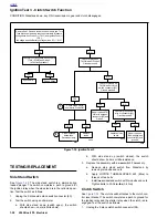
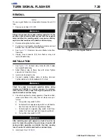
GENERAL
The voltage regulator is located under the frame (above swin-
garm on left side). The voltage regulator is not repairable.
Replace the unit if it fails.
REMOVAL
1
1
WARNING
1
WARNING
To protect against shock and accidental start-up of vehi-
cle, disconnect the negative battery cable before proced-
ing. Inadequate safety precautions could result in death
or serious injury.
1.
Disconnect negative battery cable from battery terminal.
CAUTION
When disconnecting the alternator stator wiring, pull
apart the connector by firmly grasping both connector
halves. Do not pull on leads or damage to the wires and/
or terminals could result.
2.
See
Figure 7-56.
Locate voltage regulator connector [46]
behind left footrest support. Disconnect from alternator
stator wiring. Cut cable straps if necessary.
3.
Detach charging wire from main circuit breaker.
a.
Remove seat. See Section 2.
b.
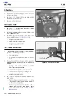
See
Figure 7-57.
Disconnect Red charging wire
from gold post of main circuit breaker.
c.
Route charging wire back to voltage regulator.
4.
Remove two mounting screws.
5.
Remove and discard voltage regulator.
INSTALLATION
1.
Apply LOCTITE THREADLOCKER 243 (Blue) to threads
of two mounting screws.
2.
See
Figure 7-57.
Attach
new
voltage regulator using two
screws. Tighten screws to 4-6 ft-lbs (5-8 Nm).
3.
Connect voltage regulator connector [46] to alternator
stator wiring. Cable tie connector halves together.
4.
Route Red charging wire to gold post on main circuit
breaker. Secure wire to frame with
new
cable straps.
1
1
WARNING
1
WARNING
After installing seat, pull upward on front of seat to be
sure it is locked in position. If seat is loose, it could shift
during vehicle operation and startle the rider, causing
loss of control of vehicle and death or serious injury.
5.
Install seat. See
2.28 SEAT
.
6.
Connect negative battery cable to battery terminal.
TIghten fastener to 60-96
in-lbs
(7-11 Nm).
7.
Test charging system. See
7.13 CHARGING SYSTEM
.
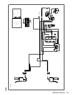
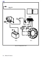
Figure 7-56. Voltage Regulator Connector [46]
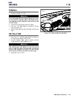
Figure 7-57. Voltage Regulator
30
A
BK
BK
BK
RD
RD
a0286x7x
Voltage
Regulator
Stator
Main Circuit Breaker (30A)
[46]
a0248x7x
Voltage
Regulator
Connector [46A]
Red Charging Wire
Screws (2)
4-6 ft-lbs
(5.4-8 Nm)
LOCTITE
®
(Blue)
243
Содержание 2002 P3
Страница 2: ......
Страница 17: ...A 15 Appendix A Tools HOME ...
Страница 32: ...C 3 Appendix C Metric Conversions HOME ...
Страница 41: ...1 8 2002 Buell P3 Maintenance HOME NOTES ...
Страница 75: ......
Страница 111: ...2 36 2002 Buell P3 Chassis HOME NOTES ...
Страница 143: ...2 68 2002 Buell P3 Chassis HOME NOTES ...
Страница 144: ...2002 Buell P3 Chassis 2 69 HOME ...
Страница 146: ......
Страница 147: ......
Страница 223: ...3 76 2002 Buell P3 Engine HOME NOTES ...
Страница 225: ......
Страница 256: ...2002 Buell P3 Fuel System 4 31 HOME ...
Страница 258: ......
Страница 259: ......
Страница 279: ...5 20 2002 Buell P3 Electric Starter HOME NOTES ...
Страница 281: ......
Страница 327: ......
Страница 398: ...2002 Buell P3 Electrical 7 71 HOME ...
Страница 399: ...SUBJECT PAGE NO A 1 TOOLS A 1 B 1 ELECTRICAL CONNECTORS B 1 C 1 METRIC INFORMATION C 1 Table Of Contents APPENDICES ...
Страница 400: ...Product 1 2 ...