


2002 Buell P3: Electrical
7-57
HOME
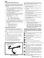
NEUTRAL INDICATOR SWITCH
7.23
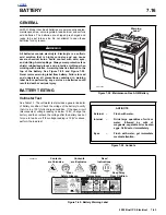
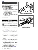
GENERAL
See
Figure 7-80.
The neutral indicator switch (1) is threaded
into the transmission portion of the right crankcase half (2); it
is immediately forward of the main drive gear shaft (3). The
sprocket cover must be removed to test the switch. If switch
requires replacement, secondary drive belt and transmission
sprocket must also be removed; there is not enough clear-
ance to allow the removal of the switch without first removing
the transmission sprocket.
A pin on the shifter drum contacts the neutral indicator switch
plunger, completing the neutral indicator circuit. The switch is
not repairable. Replace the switch if it malfunctions.
For diagnostic information, see Section
7.28 INDICATORS
.
REMOVAL/INSTALLATION
1.
Verify that the ignition key switch is turned to OFF.
2.
Remove front sprocket cover. See
2.22 SPROCKET
COVER
.
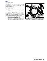
3.
See
Figure 7-80.
Place transmission in first gear.
Remove two socket head screws (7) and lockplate (6).
CAUTION
Transmission sprocket nut has left-hand threads. Turn
nut clockwise to loosen and remove from main drive
gear shaft. Transmission sprocket nut will be damaged if
turned counterclockwise to remove.
4.
Remove transmission sprocket nut (5) from main drive
gear shaft (3).
5.
Remove transmission sprocket (4) (with secondary drive
belt) from main drive gear shaft (3).
6.
Remove wire lead from neutral indicator switch (1).
Remove switch from right crankcase half (2).
7.
Install
new
neutral indicator switch.
a.
Apply a light coating of LOCTITE THREADLOCKER
243 (blue) to
new
neutral indicator switch (1)
threads.
b.
Install switch in crankcase. Tighten to 3-5 ft-lbs (4.0-
6.8 Nm).
c.
Connect wire lead to switch.
8.
Install transmission sprocket (4) (with secondary drive
belt) onto main drive gear shaft (3). See
6.16 TRANS-
MISSION SPROCKET
.
9.
Install sprocket cover. See
2.22 SPROCKET COVER
.
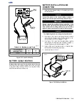
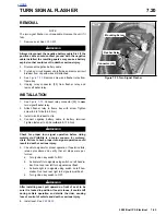
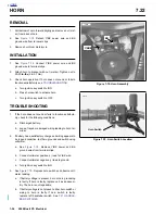
Figure 7-80. Neutral Indicator Switch
6753
1
3
2
1.
Neutral Indicator Switch
2.
Right Crankcase Half
3.
Main Drive Gear Shaft
4.
Transmission Sprocket
5.
Transmission Sprocket Nut (LH threads)
6.
Lockplate
7.
Socket Head Screw (2)
a0261x7x
3
4
6
7
5
Содержание 2002 P3
Страница 2: ......
Страница 17: ...A 15 Appendix A Tools HOME ...
Страница 32: ...C 3 Appendix C Metric Conversions HOME ...
Страница 41: ...1 8 2002 Buell P3 Maintenance HOME NOTES ...
Страница 75: ......
Страница 111: ...2 36 2002 Buell P3 Chassis HOME NOTES ...
Страница 143: ...2 68 2002 Buell P3 Chassis HOME NOTES ...
Страница 144: ...2002 Buell P3 Chassis 2 69 HOME ...
Страница 146: ......
Страница 147: ......
Страница 223: ...3 76 2002 Buell P3 Engine HOME NOTES ...
Страница 225: ......
Страница 256: ...2002 Buell P3 Fuel System 4 31 HOME ...
Страница 258: ......
Страница 259: ......
Страница 279: ...5 20 2002 Buell P3 Electric Starter HOME NOTES ...
Страница 281: ......
Страница 327: ......
Страница 398: ...2002 Buell P3 Electrical 7 71 HOME ...
Страница 399: ...SUBJECT PAGE NO A 1 TOOLS A 1 B 1 ELECTRICAL CONNECTORS B 1 C 1 METRIC INFORMATION C 1 Table Of Contents APPENDICES ...
Страница 400: ...Product 1 2 ...