


2002 Buell P3: Maintenance
1-13
HOME
1
1
WARNING
1
WARNING
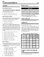
Never mix D.O.T. 4 with other brake fluids (such as D.O.T.
5). Use only D.O.T. 4 brake fluid in motorcycles that spec-
ify D.O.T. 4 fluid on the reservoir cap. Mixing different
types of fluid may adversely affect braking ability and
lead to brake failure which could result in death or seri-
ous injury
1
1
WARNING
1
WARNING
Use only fresh, uncontaminated D.O.T. 4 Fluid. Cans of
fluid that have been opened may have been contami-
nated by moisture in the air or dirt. Use of contaminated
brake fluid may adversely affect braking ability and lead
to brake failure which could result in death or serious
injury
1
1
WARNING
1
WARNING
Use only new black banjo washers (See Parts Catalog for
Part No.) with D.O.T. 4 brake fluid. Earlier silver banjo
washers are not compatible with D.O.T. 4 fluid and will
not seal properly over time. Failure to comply may
adversely affect braking ability and lead to brake failure
which could result in death or serious injury.
NOTE
Hydraulic brake fluid bladder-type pressure equipment can
be used to fill the brake master cylinder through the bleeder
valve if master cylinder reservoir cover is removed to prevent
pressurization.
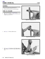
1.
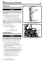
Install end of a length of plastic tubing over caliper
bleeder valve; place other end in a clean container.
Stand motorcycle upright.
a. See
Figure 1-6.
Front brake bleeder valve.
b.
See
Figure 1-7.
Rear brake bleeder valve.
CAUTION
Cover molded-in-color surfaces and right handlebar
switches and use care when removing brake reservoir
cover and adding D.O.T. 4 brake fluid. Spilling D.O.T. 4
brake fluid on molded-in-color surfaces will result in cos-
metic damage. Spilling brake fluid on switches may ren-
der them inoperative.
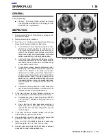
2.
Add
D.O.T. 4 BRAKE FLUID
to master cylinder reser-
voir. Do not reuse brake fluid.
a.
Remove two screws from front master cylinder cover.
Bring fluid level to within 0.125 in. (3.2 mm) of
molded boss inside front master cylinder.
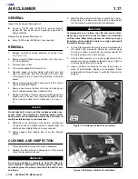
b.
Remove cap and gasket from rear master cylinder
reservoir. Bring fluid level to between upper and
lower marks on reservoir.
3.
Depress, release and then hold brake lever/pedal to build
up hydraulic pressure.
4.
Open bleeder valve (metric) about 1/2-turn counterclock-
wise; brake fluid will flow from bleeder valve and through
tubing. When brake lever/pedal has moved 1/2-3/4 of its
full range of travel, close bleeder valve (clockwise). Allow
brake lever/pedal to return slowly to its released position.
5.
Repeat Steps 2-4 until all air bubbles are purged.
6.
Tighten bleeder valve (metric) to 3-5 ft-lbs (4.1-6.8 Nm).
7.
Verify master cylinder fluid level as described in Step 2.
1
1
WARNING
1
WARNING
Always test motorcycle brakes at low speed after servic-
ing or bleeding system. If brakes are not operating prop-
erly, or braking efficiency is poor, testing at high speeds
could result in death or serious injury.
8.
Attach covers to master cylinder reservoirs.
a.
Tighten screws on master cylinder reservoir cover to
9-13
in-lbs
(1.0-1.5 Nm).
b.
Tighten cap on rear master cylinder securely.
REAR BRAKE PEDAL
1
1
WARNING
1
WARNING
Always test motorcycle brakes at low speed after servic-
ing or bleeding system. If brakes are not operating prop-
erly, or braking efficiency is poor, testing at high speeds
could result in death or serious injury.
Check rear brake pedal for proper operation.
●
Before every ride.
●
At the 1000 mile (1600 km) service interval and at
every 5000 mile (8000 km) service interval thereaf-
ter.
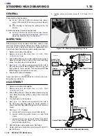
1.
Inspect locknut installation. Locknut should be flush with
top surface of clevis.
2.
Observe the position of brake pedal and foot peg. Brake
pedal should be set so top surface of brake pedal is even
with top surface of foot peg.
3.
Set brake pedal height.
a. Loosen
locknut.
b.
Turn rod adjuster to obtain correct position.
c. Tighten
locknut.
NOTE
Brake pedal has no freeplay adjustment.
Figure 1-8. Brake Fluid Level - Front Reservoir
Brake fluid level
a0214x2x
Содержание 2002 P3
Страница 2: ......
Страница 17: ...A 15 Appendix A Tools HOME ...
Страница 32: ...C 3 Appendix C Metric Conversions HOME ...
Страница 41: ...1 8 2002 Buell P3 Maintenance HOME NOTES ...
Страница 75: ......
Страница 111: ...2 36 2002 Buell P3 Chassis HOME NOTES ...
Страница 143: ...2 68 2002 Buell P3 Chassis HOME NOTES ...
Страница 144: ...2002 Buell P3 Chassis 2 69 HOME ...
Страница 146: ......
Страница 147: ......
Страница 223: ...3 76 2002 Buell P3 Engine HOME NOTES ...
Страница 225: ......
Страница 256: ...2002 Buell P3 Fuel System 4 31 HOME ...
Страница 258: ......
Страница 259: ......
Страница 279: ...5 20 2002 Buell P3 Electric Starter HOME NOTES ...
Страница 281: ......
Страница 327: ......
Страница 398: ...2002 Buell P3 Electrical 7 71 HOME ...
Страница 399: ...SUBJECT PAGE NO A 1 TOOLS A 1 B 1 ELECTRICAL CONNECTORS B 1 C 1 METRIC INFORMATION C 1 Table Of Contents APPENDICES ...
Страница 400: ...Product 1 2 ...