


7-68
2002 Buell P3: Electrical
HOME
MAIN WIRING HARNESS
7.29
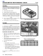
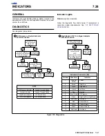
GENERAL
The main wiring harness runs from the front of the motorcy-
cle (behind dash) to the rear of the frame tray under the seat
where it connects to the tail lamp/turn signal mini-harness.
REMOVAL
1.
Remove seat. See
2.28 SEAT
.
1
1
WARNING
1
WARNING
To protect against shock and accidental start-up of vehi-
cle, disconnect the negative battery cable before proced-
ing. Inadequate safety precautions could result in death
or serious injury.
1
1
WARNING
1
WARNING
Always disconnect the negative cable first. If the positive
cable should contact ground with the negative cable
installed, the resulting sparks may cause a battery explo-
sion which could result in death or serious injury.
2.
Disconnect battery cables, negative cable first.
3.
Remove battery. See
7.16 BATTERY
.
4.
Remove fuel tank. See
4.2 FUEL TANK COVER/FUEL
TANK
.
5.
Remove windscreen. See
2.26 WINDSCREEN
.
6.
Remove headlamp housing and disconnect connector
[38]. See
7.17 HEADLAMP
.
7.
Note location of cable ties and cut three cable ties on
frame backbone that secure main wiring harness to
frame. Disconnect harness from T-studs.
8.
Disconnect speedometer connector [39].
9.
Disconnect right and left handlebar switch connectors
[22] and [24], front brake switch blade connectors [170]
and clutch switch connector [95].
10. Tag and disconnect right and left front turn signal bullet
connectors.
11. Disconnect ignition switch connector [33].
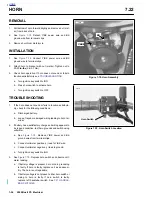
12. Note location of cable tie and cut cable tie on horn wire
and remove two blade connectors [122] from horn.
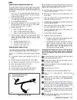
13. See
Figure 7-95.
Unhook connector [10] from the T-stud
on the left side of the frame backbone.
14. Note location of cable tie and cut cable tie on ignition coil
and TP Sensor/Auto-Enrichener and Ignition Module har-
ness.
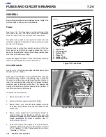
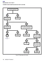
15. See
Figure 7-96.
Disconnect ignition coil connector [83]
at coil.
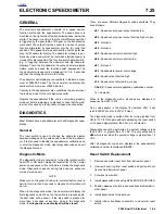
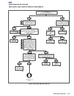
16. See
Figure 7-97.
Disconnect TP Sensor/Auto-Enrichener
connector [88] under frame backbone.
17. Disconnect starter connector [128] at starter solenoid.
18. See
Figure 7-95.
Disconnect ignition connector [10] on
left side of frame backbone.
19. Feed harness through frame and upper tie bar mount.
Figure 7-95. Ignition Connector [10]
Figure 7-96. Coil Connector [83]
Figure 7-97. TP Sensor/Auto-Enrichener Connector [88]
7813
Connector [10]
7814
Connector [83]
a0264x7x
Throttle Position
Sensor
Connector [88]
Auto-Enrichener
Содержание 2002 P3
Страница 2: ......
Страница 17: ...A 15 Appendix A Tools HOME ...
Страница 32: ...C 3 Appendix C Metric Conversions HOME ...
Страница 41: ...1 8 2002 Buell P3 Maintenance HOME NOTES ...
Страница 75: ......
Страница 111: ...2 36 2002 Buell P3 Chassis HOME NOTES ...
Страница 143: ...2 68 2002 Buell P3 Chassis HOME NOTES ...
Страница 144: ...2002 Buell P3 Chassis 2 69 HOME ...
Страница 146: ......
Страница 147: ......
Страница 223: ...3 76 2002 Buell P3 Engine HOME NOTES ...
Страница 225: ......
Страница 256: ...2002 Buell P3 Fuel System 4 31 HOME ...
Страница 258: ......
Страница 259: ......
Страница 279: ...5 20 2002 Buell P3 Electric Starter HOME NOTES ...
Страница 281: ......
Страница 327: ......
Страница 398: ...2002 Buell P3 Electrical 7 71 HOME ...
Страница 399: ...SUBJECT PAGE NO A 1 TOOLS A 1 B 1 ELECTRICAL CONNECTORS B 1 C 1 METRIC INFORMATION C 1 Table Of Contents APPENDICES ...
Страница 400: ...Product 1 2 ...