


2002 Buell P3: Engine
3-29
HOME
Replacing Valve Guides
Valve guide replacement, if necessary, must be done before
valve seat is ground. It is the valve stem hole in valve guide
that determines seat grinding location. Valve stem-to-valve
guide clearances are listed in
Table 3-5.
If valve stems and/or
guides are worn beyond limits, install
new
parts.
1.
To remove shoulderless guides, press or tap guides
toward combustion chamber using DRIVER HANDLE
AND REMOVER (Part No. HD-34740).
2.
Clean and measure valve guide bore in head.
3.
Measure outer diameter of a new standard valve guide.
The guide diameter should be 0.0020-0.0033 in.
(0.0508-0.0838 mm). larger than bore in head. If it is not,
select one of the following oversizes: +0.001 in. (+0.025
mm), +0.002 in. (+0.051 mm) or +0.003 in. (+0.076 mm)
(intake and exhaust).
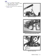
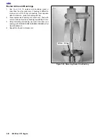
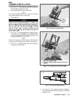
4.
See
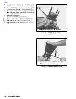
Figure 3-55.
Install shoulderless guides using
VALVE GUIDE INSTALLATION TOOL (Part No. HD-
34731) and DRIVER HANDLE (Part No. HD-34740).
Press or drive guide until the tool touches the machined
surface surrounding the guide. At this point, the correct
guide height has been reached.
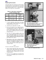
5.
Ream guides to final size or within 0.0010 in.
(0.0254 mm) of final size using VALVE GUIDE REAMER
(Steel, Part No. HD-39932 or Carbide, Part No. HD-
39932-CAR). Use REAMER LUBRICANT (Part No. HD-
39964) or liberal amounts of suitable cutting oil to pre-
vent reamer chatter.
NOTE
The hone is not intended to remove material.
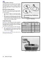
6.
Apply the proper surface finish to the valve guide bores
using the VALVE GUIDE HONE (Part No. HD-34723).
Lubricate hone with honing oil. Driving hone with an
electric drill, work for a crosshatch pattern with an angle
of approximately 60°.
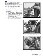
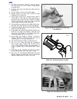
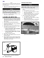
7.
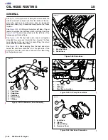
See
Figure 3-56.
Thoroughly clean valve guide bores
using VALVE GUIDE BRUSH) (Part No. HD-34751) and
hot soapy water.
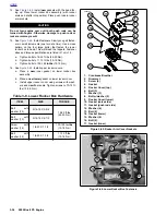
Table 3-5. Valve Stem Clearances
and Service Wear Limits
VALVE
CLEARANCE
SERVICE WEAR
LIMIT
Exhaust
0.0015-0.0033 in.
(0.0381-0.0838 mm)
0.0040 in.
(0.1016 mm)
Intake
0.008-0.0026 in.
(0.203-0.0660 mm)
0.0035 in.
(0.0889 mm)
Figure 3-55. Installing Shoulderless Valve Guide
Figure 3-56. Cleaning Valve Guides
5692
1.
Driver Handle (Part No. HD-34740)
2.
Valve Guide Installation tool (Part No. HD-34731)
3.
Cylinder Head Stand (Part No. HD-39782)
1
2
3
5695
1.
Valve Guide Brush (Part No. HD-34751)
2.
Cylinder Head Holding Fixture
(Part No. HD-39786)
1
2
Содержание 2002 P3
Страница 2: ......
Страница 17: ...A 15 Appendix A Tools HOME ...
Страница 32: ...C 3 Appendix C Metric Conversions HOME ...
Страница 41: ...1 8 2002 Buell P3 Maintenance HOME NOTES ...
Страница 75: ......
Страница 111: ...2 36 2002 Buell P3 Chassis HOME NOTES ...
Страница 143: ...2 68 2002 Buell P3 Chassis HOME NOTES ...
Страница 144: ...2002 Buell P3 Chassis 2 69 HOME ...
Страница 146: ......
Страница 147: ......
Страница 223: ...3 76 2002 Buell P3 Engine HOME NOTES ...
Страница 225: ......
Страница 256: ...2002 Buell P3 Fuel System 4 31 HOME ...
Страница 258: ......
Страница 259: ......
Страница 279: ...5 20 2002 Buell P3 Electric Starter HOME NOTES ...
Страница 281: ......
Страница 327: ......
Страница 398: ...2002 Buell P3 Electrical 7 71 HOME ...
Страница 399: ...SUBJECT PAGE NO A 1 TOOLS A 1 B 1 ELECTRICAL CONNECTORS B 1 C 1 METRIC INFORMATION C 1 Table Of Contents APPENDICES ...
Страница 400: ...Product 1 2 ...