


7-28
2002 Buell P3: Electrical
HOME
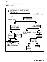
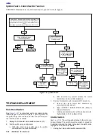
Ignition Test 3 - Clutch Switch Function
CONDITION: Sidestand down, key ON, transmission in gear and clutch disengaged
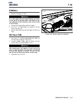
TESTING/REPLACEMENT
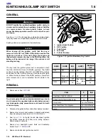
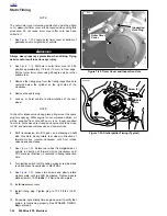
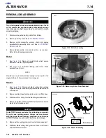
Side Stand Switch
See
Figure 7-33.
The side stand switch is a simple spring
loaded plunger. The switch completes a path to ground for
the ignition relay when the side stand is in the retracted posi-
tion. Test the switch as follows:
1.
Unplug the 2-place side stand switch connector [60].
2.
Test the switch using an ohmmeter.
a. With side stand down (switch open), the switch
should show
∞
ohms (infinite ohms).
b.
With side stand up (switch closed), the switch
should show 0 ohms or little resistance.
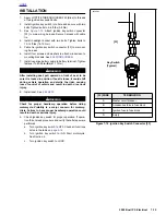
3.
Replace the assembly with a
new
switch if necessary.
a. Remove side stand switch from Sidestand by
removing two bolts and nuts.
b.
Apply LOCTITE THREADLOCKER 243 (Blue) to
threads of two bolts.
c. Install
new
sidestand switch with two bolts and nuts.
Tighten bolts to 30-36
in-lbs
(3-4 Nm).
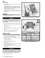
Clutch Switch
See
Figure 7-34.
The clutch switch attaches to the clutch con-
trol lever bracket. The switch completes a path to ground for
the ignition relay and the starter relay when the clutch is dis-
engaged. Test the switch as follows:
1.
Unplug the 2-place clutch switch connector [95].
Figure 7-32. Ignition Test 3
YES
YES
Check for ground on
TN/GN wire of clutch
switch connector [95].
Ground present?
Check for ground on
TN/GN wire of Diode 2.
Ground present?
YES
Check Diode 2 with
ohmmeter. Diode OK?
YES
Diode installed
backwards.
Reverse polarity.
Replace
diode.
YES
Repair open on TN/
GN wire between
connector [95] and
Diode 2.
NO
Replace clutch
switch.
NO
NO
Repair open on
BK wire between
connector [95] and
ground.
NO
5071
5072
5073
5074
5075
1
2
Check for ground on BK
wire of connector [95].
Ground present?
NO
NO
Repair Wiring
System OK.
YES
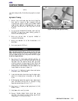
Remove Seat. Remove fuse block from frame tab. Turn
fuse block upside down to access terminals. Measure
voltage between Diode 2 (-) (TN/Y) and Ignition Fuse (+)
(GY).
Is Voltage equal to Battery Voltage minus 0.7 +/- 0.1V?
Check for continuity between Socket B
(TN/Y) [134B] and Diode 2.
Is Continuity present?
Содержание 2002 P3
Страница 2: ......
Страница 17: ...A 15 Appendix A Tools HOME ...
Страница 32: ...C 3 Appendix C Metric Conversions HOME ...
Страница 41: ...1 8 2002 Buell P3 Maintenance HOME NOTES ...
Страница 75: ......
Страница 111: ...2 36 2002 Buell P3 Chassis HOME NOTES ...
Страница 143: ...2 68 2002 Buell P3 Chassis HOME NOTES ...
Страница 144: ...2002 Buell P3 Chassis 2 69 HOME ...
Страница 146: ......
Страница 147: ......
Страница 223: ...3 76 2002 Buell P3 Engine HOME NOTES ...
Страница 225: ......
Страница 256: ...2002 Buell P3 Fuel System 4 31 HOME ...
Страница 258: ......
Страница 259: ......
Страница 279: ...5 20 2002 Buell P3 Electric Starter HOME NOTES ...
Страница 281: ......
Страница 327: ......
Страница 398: ...2002 Buell P3 Electrical 7 71 HOME ...
Страница 399: ...SUBJECT PAGE NO A 1 TOOLS A 1 B 1 ELECTRICAL CONNECTORS B 1 C 1 METRIC INFORMATION C 1 Table Of Contents APPENDICES ...
Страница 400: ...Product 1 2 ...