


d
059
40
.f
m
MAINTENANCE MANUAL
BRP-Powertrain
Effectivity: 912 i Series
Edition 1/Rev. 0
76-50-00
Page 18
July 01/2012
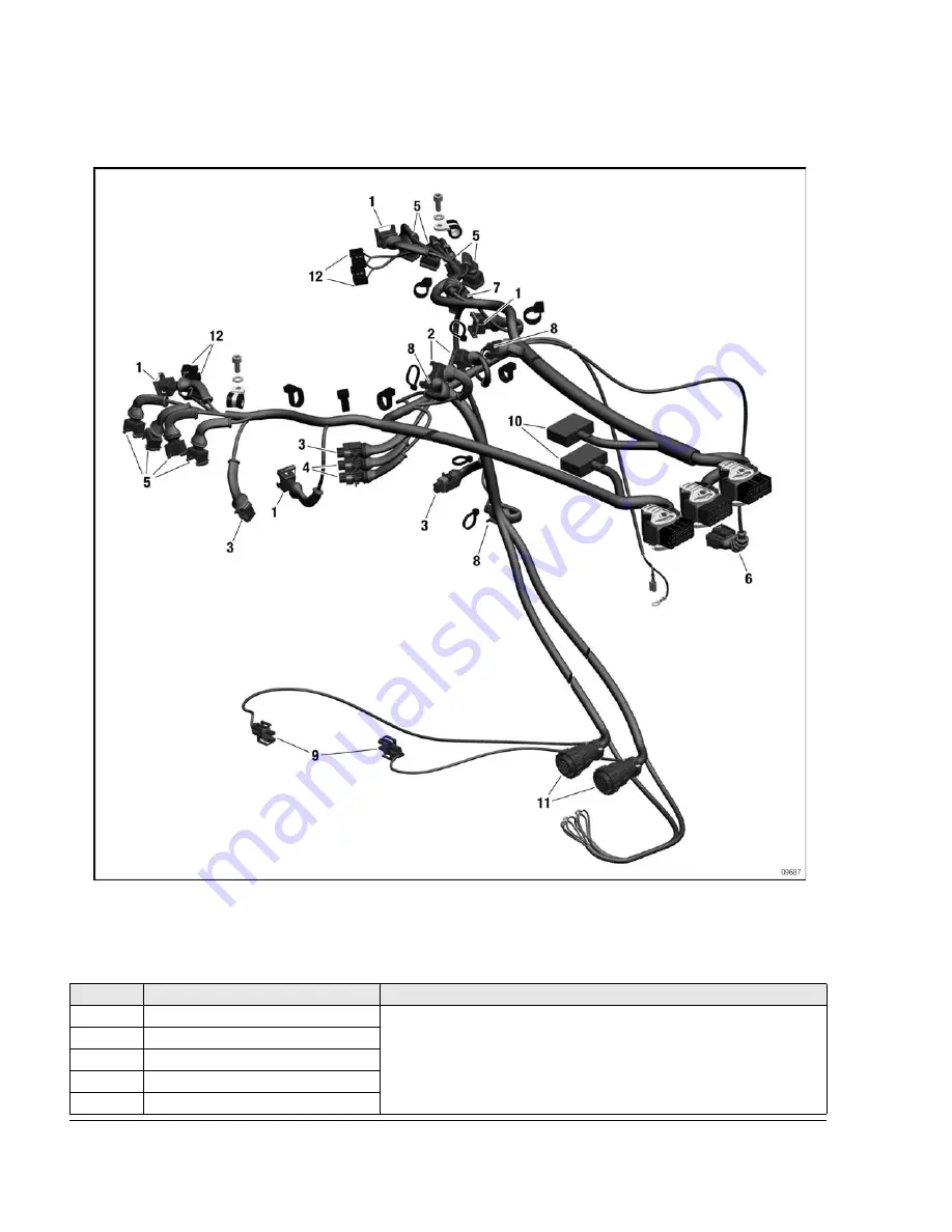
Pos.
Part no. of connector set
Corresponding tool
1
881290
Crimping pliers TYCO 539 635-1
Jaws TYCO 539 737-2
Disassembly tool TYCO 1-1579007-6
2
881292
3
881296
4
881298
5
881300
NOTE:
If the wire is broken or the connector is defective, the damage can be repaired.
The cable must be long enough if the connector is cut off.
Repair with the tools described here must comply with the aircraft standard of the
respective country.
Содержание Rotax 912 i Series
Страница 14: ...d06671 fm MAINTENANCE MANUAL BRP Rotax Effectivity 912 i Series Edition 1 Rev 0 TOA Page 4 July 01 2012 NOTES ...
Страница 110: ...d05933 fm MAINTENANCE MANUAL BRP Powertrain Effectivity 912 i Series Edition 1 Rev 0 71 00 00 Page 2 July 01 2012 NOTES ...
Страница 136: ...d05342 fm MAINTENANCE MANUAL BRP Powertrain Effectivity 912 i Series Edition 1 Rev 0 72 00 00 Page 4 July 01 2012 NOTES ...
Страница 140: ...d06672 fm MAINTENANCE MANUAL BRP Rotax Effectivity 912 i Series Edition 1 Rev 3 72 10 00 Page 4 July 01 2018 Components ...
Страница 155: ...d06672 fm MAINTENANCE MANUAL BRP Rotax Effectivity 912 i Series Edition 1 Rev 3 72 10 00 Page 19 July 01 2018 NOTES ...
Страница 168: ...d06672 fm MAINTENANCE MANUAL BRP Rotax Effectivity 912 i Series Edition 1 Rev 3 72 10 00 Page 32 July 01 2018 NOTES ...
Страница 170: ...d05344 fm MAINTENANCE MANUAL BRP Powertrain Effectivity 912 i Series Edition 1 Rev 0 72 20 00 Page 2 July 01 2012 NOTES ...
Страница 214: ...d05935 fm MAINTENANCE MANUAL BRP Powertrain Effectivity 912 i Series Edition 1 Rev 0 72 30 10 Page 2 July 01 2012 ...
Страница 216: ...d05935 fm MAINTENANCE MANUAL BRP Powertrain Effectivity 912 i Series Edition 1 Rev 0 72 30 10 Page 4 July 01 2012 NOTES ...
Страница 223: ...d05935 fm MAINTENANCE MANUAL BRP Powertrain Effectivity 912 i Series Edition 1 Rev 2 72 30 10 Page 11 July 01 2014 ...
Страница 234: ...d05347 fm MAINTENANCE MANUAL BRP Powertrain Effectivity 912 i Series Edition 1 Rev 0 73 00 00 Page 2 July 01 2012 NOTES ...
Страница 276: ...d05349 fm MAINTENANCE MANUAL BRP Powertrain Effectivity 912 i Series Edition 1 Rev 0 74 00 00 Page 4 July 01 2012 NOTES ...
Страница 282: ...d05937 fm MAINTENANCE MANUAL BRP Powertrain Effectivity 912 i Series Edition 1 Rev 0 74 20 00 Page 6 July 01 2012 NOTES ...
Страница 318: ...d06674 fm MAINTENANCE MANUAL BRP Powertrain Effectivity 912 i Series Edition 1 Rev 0 76 10 00 Page 2 July 01 2012 NOTES ...
Страница 414: ...d05356 fm MAINTENANCE MANUAL BRP Powertrain Effectivity 912 i Series Edition 1 Rev 0 78 00 00 Page 4 July 01 2012 NOTES ...
Страница 422: ...d05357 fm MAINTENANCE MANUAL BRP Powertrain Effectivity 912 i Series Edition 1 Rev 0 78 10 00 Page 8 July 01 2012 NOTES ...
Страница 425: ...d05941 fm MAINTENANCE MANUAL BRP Powertrain Effectivity 912 i Series Edition 1 Rev 0 79 00 00 Page 3 July 01 2012 ...
Страница 426: ...d05941 fm MAINTENANCE MANUAL BRP Powertrain Effectivity 912 i Series Edition 1 Rev 0 79 00 00 Page 4 July 01 2012 NOTES ...
Страница 450: ...d05359 fm MAINTENANCE MANUAL BRP Powertrain Effectivity 912 i Series Edition 1 Rev 0 80 00 00 Page 2 July 01 2012 ...
Страница 456: ...d05359 fm MAINTENANCE MANUAL BRP Powertrain Effectivity 912 i Series Edition 1 Rev 0 80 00 00 Page 8 July 01 2012 NOTES ...
Страница 457: ......