Element
Description
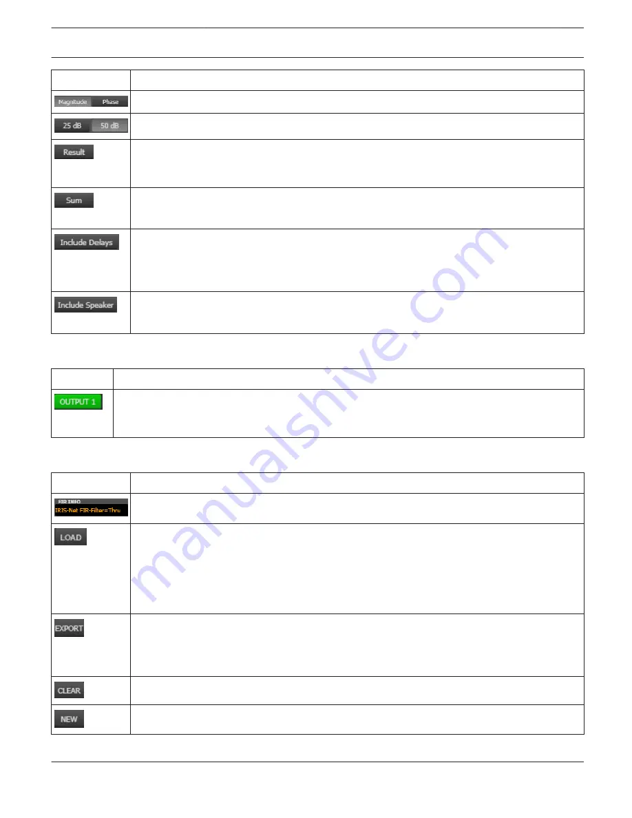
Switch for displaying frequency response (magnitude) or phase response (phase)
Switch for scaling the dB-axis to 25 dB (± 12.5 dB) or to 50 dB (± 25 dB)
Displays the resulting transfer function of all filter and level trim settings and therefore graphically
displaying the audible result at the sound system processor outputs. The audible result is displayed
in bright colors while all ”electrical” graphs are drawn in dark colors.
The ”Sum” switch causes display of the summed signal of the output channels. If the ”Sum ” switch
is not pressed the output channels’ transfer functions are indicated separately.
Switch for including programmed delays in the frequency or phase response indication. The delays
mainly affect phase response indication. Indicating the sound system processor channels’ summed
signals reveals very clearly the effect that the delays have on the frequency response, e.g. as notch
filter effect.
Switch for additionally indicating measured speaker transfer functions. For this function to be
effective you first have to load speaker data in the ”Speaker” tab.
Channel Selection
Element
Description
Switch for selecting output 1, 2, 3, 4. 5 or output 6 for filter editing.
A click with the right mouse button opens the ”Copy & Paste” menu, which allows convenient copying
of all FIR filter settings of the corresponding output to any other FIR filter within the same project.
Channel Parameters
Element
Description
Description of the FIR filter currently in use.
After clicking onto LOAD the "Open File..." dialog box appears. Enter the correct path of the
directory in which the desired file is located and select the desired FIR file to be opened. This loads
and afterwards displays all FIR filter parameters that are stored within that file.
CAUTION: The loaded FIR filter file becomes instantly audible when in on-line mode. Be sure to
select the desired FIR file with the correct set of parameters. In the worst case, this could lead
to severe damage to the connected loudspeaker cabinets due to improper signal processing!
After clicking on EXPORT FIR a "Save File..." dialog box appears. Enter the correct path of the
directory that you want to save the data in. Enter a file name (without extension). Click on the SAVE
button to store the FIR filter parameters together with the corresponding file name. ".gkf" is
automatically added as file extension.
Clears the current FIR filter settings. A Default-FIR-Filter (Thru) is activated instead.
Clicking on the NEW button opens the Filter Design dialog.
IRIS-Net
DIGITAL SOUND PROCESSOR | en 683
Bosch Security Systems B.V.
User Manual
2017.05 | 3.20 | F.01U.119.956
Содержание IRIS-Net
Страница 1: ...IRIS Net en User Manual ...
Страница 2: ......
Страница 146: ...IRIS Net REMOTE AMPLIFIER en 146 Bosch Security Systems B V User Manual 2017 05 3 20 F 01U 119 956 ...
Страница 148: ...IRIS Net REMOTE AMPLIFIER en 148 Bosch Security Systems B V User Manual 2017 05 3 20 F 01U 119 956 ...
Страница 151: ...IRIS Net REMOTE AMPLIFIER en 151 Bosch Security Systems B V User Manual 2017 05 3 20 F 01U 119 956 ...
Страница 153: ...Layer 5 Control Page IRIS Net REMOTE AMPLIFIER en 153 Bosch Security Systems B V User Manual 2017 05 3 20 F 01U 119 956 ...
Страница 648: ...IRIS Net DIGITAL SOUND PROCESSOR en 648 Bosch Security Systems B V User Manual 2017 05 3 20 F 01U 119 956 ...
Страница 693: ...IRIS Net DIGITAL SOUND PROCESSOR en 693 Bosch Security Systems B V User Manual 2017 05 3 20 F 01U 119 956 ...
Страница 992: ......
Страница 993: ......


