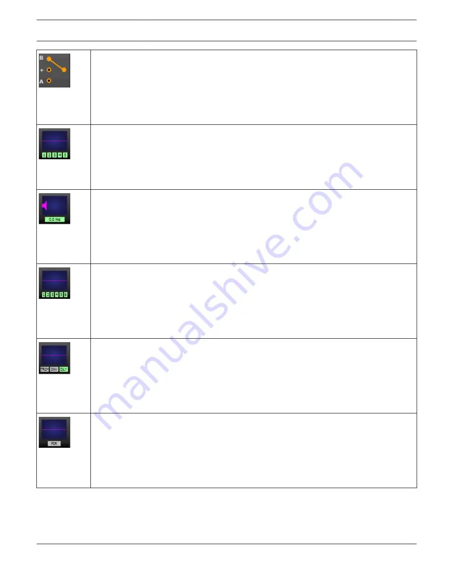
ROUTING Block:
Here you can assign the output channel routing. The circles next to A and B allow selection of the
input signal for the corresponding output channel. The circle next to the + allows selection of the
summed input signal for the corresponding output channel.
A click with the right mouse button onto routing block opens the Copy & Paste menu of all DSP
settings, which allows copying all DSP parameters of an amplifier to any other RCM-28 amplifier
within the same project.
ARRAY PEQ Block:
The ARRAY PEQ block displays the 5 Array EQs of the corresponding output channel. The 5 LEDs
indicate which EQ-bands are being used while the graph shows the frequency response of the PEQ
block. A single click with the left mouse button onto this block opens the Array Parametric EQ page.
Clicking with the right mouse button opens the Copy & Paste menu, which allows copying all
parameters of the corresponding ARRAY PEQ block to any other EQ block within the same project.
ARRAY DELAY Block:
This displays the Array Delay of the output channels. The delay-value is displayed together with the
measurement unit. The graph shows the approximate amount of delay being applied. A single click
with the left mouse button onto this block opens the Array Delay page.
Clicking with the right mouse button opens the Copy & Paste menu, which allows copying all
parameters of the corresponding Delay block to any other ARRAY DELAY block within the same
project.
SPEAKER PROCESSING PEQ Block:
The SPEAKER PROCESSING PEQ block displays the 6 Channel EQs of the corresponding output
channel. The 6 LEDs indicate which EQ-bands are being used while the graph shows the frequency
response of the PEQ block. A single click with the left mouse button onto this block opens the Out-
put Parametric EQ page.
Clicking with the right mouse button opens the Copy & Paste menu, which allows copying all
parameters of the corresponding Speaker EQ block to any other EQ block within the same project.
SPEAKER PROCESSING X-OVER Block:
This block represents the crossover within the corresponding output channel. The graph shows the
frequency response that results from the set X- Over parameters. Three additional LEDs indicate the
status of gain trim (TRIM), polarity (INV) and delay (DLY). A single click with the left mouse but- ton
onto this block opens the Output X-Over page. Clicking with the right mouse button opens the Copy
& Paste menu, which allows copying all parameters of the corresponding X-Over block to any other
X-Over block within the same project.
SPEAKER PROCESSING FIR FILTER Block:
This block represents the FIR Filter within the corresponding output channel. The graph shows the
frequency response that results from the set FIR parameters. The LED indicates if the FIR Filter is
being used. A single click with the left mouse button onto this block opens the Output FIR page.
Clicking with the right mouse button opens the Copy & Paste menu, which allows copying all
parameters of the corresponding FIR Filter block to any other FIR Filter block within the same
project.
IRIS-Net
REMOTE AMPLIFIER | en 259
Bosch Security Systems B.V.
User Manual
2017.05 | 3.20 | F.01U.119.956
Содержание IRIS-Net
Страница 1: ...IRIS Net en User Manual ...
Страница 2: ......
Страница 146: ...IRIS Net REMOTE AMPLIFIER en 146 Bosch Security Systems B V User Manual 2017 05 3 20 F 01U 119 956 ...
Страница 148: ...IRIS Net REMOTE AMPLIFIER en 148 Bosch Security Systems B V User Manual 2017 05 3 20 F 01U 119 956 ...
Страница 151: ...IRIS Net REMOTE AMPLIFIER en 151 Bosch Security Systems B V User Manual 2017 05 3 20 F 01U 119 956 ...
Страница 153: ...Layer 5 Control Page IRIS Net REMOTE AMPLIFIER en 153 Bosch Security Systems B V User Manual 2017 05 3 20 F 01U 119 956 ...
Страница 648: ...IRIS Net DIGITAL SOUND PROCESSOR en 648 Bosch Security Systems B V User Manual 2017 05 3 20 F 01U 119 956 ...
Страница 693: ...IRIS Net DIGITAL SOUND PROCESSOR en 693 Bosch Security Systems B V User Manual 2017 05 3 20 F 01U 119 956 ...
Страница 992: ......
Страница 993: ......


