General Parameters
Element
Default
Range
Description
dBu
dBu /
Volts
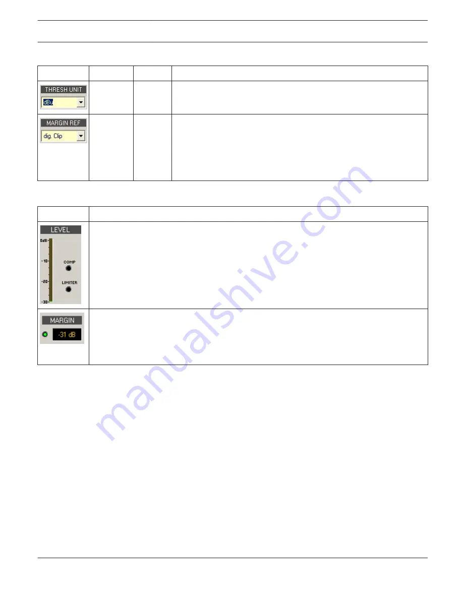
This lets you select the unit for the threshold parameter. The selected
setting applies to compressor and limiter as well.
dig. Clip
dig. Clip,
Limiter
Thresh
This lets you set the absolute level for margin indication. You can select
between ”Digital Clip” (relates to
+21 dBu) and ”Limiter Threshold”.
The margin level indicates the distance between signal level and the set
absolute level. The displayed mar- gin always relates to the highest actual
signal level reading.
Indications
Element
Description
These indicator shows the reduction in dB that is applied to the audio signal by the compressor
(COMP) or limiter. Level reduction is indicated as vertical yellow bar graph.
The margin level indicates the distance between signal level and the set absolute level. The displayed
margin relates to the highest actual signal level reading since the last reset of the indicator. The LED
changes from green to red as soon as the signal level reaches or exceeds the set absolute level
(Digital Clip / Limiter Threshold). A click with the right mouse button onto the margin level followed
by click onto Reset re-sets indication.
Editing Compressor / Limiter Parameters by “Dragging the Mouse” in the Graphics Display
Active compressors or limiters (bypass button is not engaged) are indicated by a white dot in the graphics display
representing its function. A click with the left mouse button onto this dot and keeping the mouse button pressed down
lets you set the threshold for the corresponding compressor or limiter by vertically dragging the mouse. A click with the
right mouse button onto the white dot of a compressor and keeping the mouse button pressed down lets you edit the
ratio of compression.
A compressor’s / limiter’s title “lights” in color as soon as the mouse cursor is positioned on top of the corresponding
white dot to provide improved overview and handling.
Speaker
The Speaker Dialog offers the possibility to load the datasets of different loudspeaker systems, assign it to the sound
system processor channels and display the acoustic results. The speaker system datasets, which are provided as
“speaker files” (*.spk), contain factory-measured frequency- and phase responses of loudspeaker systems. The speaker
data as well as any settings made in this window have no direct influence on the transfer function of the sound system
processor. Nevertheless, they provide the user with the possibility for creating loudspeaker systems presets of a higher
IRIS-Net
DIGITAL SOUND PROCESSOR | en 573
Bosch Security Systems B.V.
User Manual
2017.05 | 3.20 | F.01U.119.956
Содержание IRIS-Net
Страница 1: ...IRIS Net en User Manual ...
Страница 2: ......
Страница 146: ...IRIS Net REMOTE AMPLIFIER en 146 Bosch Security Systems B V User Manual 2017 05 3 20 F 01U 119 956 ...
Страница 148: ...IRIS Net REMOTE AMPLIFIER en 148 Bosch Security Systems B V User Manual 2017 05 3 20 F 01U 119 956 ...
Страница 151: ...IRIS Net REMOTE AMPLIFIER en 151 Bosch Security Systems B V User Manual 2017 05 3 20 F 01U 119 956 ...
Страница 153: ...Layer 5 Control Page IRIS Net REMOTE AMPLIFIER en 153 Bosch Security Systems B V User Manual 2017 05 3 20 F 01U 119 956 ...
Страница 648: ...IRIS Net DIGITAL SOUND PROCESSOR en 648 Bosch Security Systems B V User Manual 2017 05 3 20 F 01U 119 956 ...
Страница 693: ...IRIS Net DIGITAL SOUND PROCESSOR en 693 Bosch Security Systems B V User Manual 2017 05 3 20 F 01U 119 956 ...
Страница 992: ......
Страница 993: ......


