


1
0
.0
Electrical System
1
0
.1
Electrical System Structure
The system has two CAN Networks and an analogue system. The systems are broken down as listed below:
•
CAN 0 – Communication between the controller, the joystick, the HMI (Human Machine Interface) and the Telemetry unit if fitted.
•
CAN 1 – Communication between all the PVG solenoids, the pressure transducers, the controller and the rotary transducers.
•
Analogue – Communication between the inductive switches and the controller and between the selector valves and the controller.
The table below gives a brief key to the electrical schematics which should assist with fault finding should it be necessary within the
CAN line (purple cable)
(
Fig. 15
5
)
CAN 0 Network:
CAN 0 communicates between the Joystick, the HMI, the Controller and the Telemetry unit if fitted.
There is one terminator connected in the ECU box through an M12 connector. This is where the telemetry unit would be fitted if the option is
available.
The other terminator is connected to the cab harness. This connector is used to upload software and for Diagnostics. The CG150 is used to
connect the Transtacker to your laptop (Service Tool).
CAN 1 Network:
CAN 1 communicates between the solenoids on the valve block, the pressure transducers and rotary sensors. One CAN terminator is located on
the pickup by the rotary sensor and the other is located on the a-frame near the A-Frame Rotate rotary sensor.
To quickly identify the wiring looms around the machine they are all connected using a purple looms and ‘splitters’ which act a tree and branch off
for each of the sensors with a 300mm long cable.
The first
(CAN A)
tree goes from slice 11 on the valve block to the pickup rotary sensor.
The second
(CAN B)
tree goes to the top of the Transtacker and runs all the way from the ECU to the turntable rotary sensor (
Refer to
Fig.
15
7
on the next page for lengths and positioning of
sensors on
the CAN line
).
Analogue Network:
Analogue communicates between all of the 15 proximity sensors and the 2 different selector valve blocks on the Transtacker. This system is run
off the black custom made harnesses. Within this Analogue Network there is 3 different trees which run through the Transtacker.
The first tree runs to the Bump Paddle and the Platform Bed Full sensor.
The second tree runs underneath the platform that ends up at the Side Gates Open Left and Right Proximity sensors.
The third tree runs all the way up through the IGUS chain and ends up at the turntable full proximity sensor.
On the Transtacker there is 8 fuses.
Fig. 1
5
6
is a list of the Fuses, their locations and their respective function.
F1
5A Blade
ECU box
Power to Screen and Joystick
F2
10A Blade
ECU box
Power to Controller
F3
5A Blade
ECU box
Power to Loom 3
F4
5A Blade
ECU box
Power to Loom 1 and 2
F5
5A Blade
ECU box
Power to CAN B
F6
5A Blade
ECU box
Power to CAN A
F12
30A Blade
Cab Loom Power from Battery
F11
5A
Blade
ECU box
Power to E-Stop and Switch
No.
Type of Fuse
Location
Function
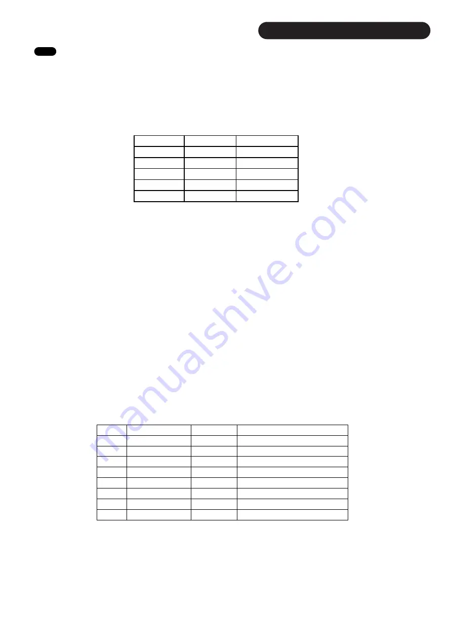
Pin Location
Colour
Function
1
Metal Shield
CAN Shield
2
Red
Supply Voltage
3
Black
Ground
4
Brown
CAN High
5
Grey
CAN Low
Fig. 1
5
5
Fig. 1
5
6
50
Содержание Transtacker 4100
Страница 61: ...58...
Страница 62: ...59...
Страница 63: ...11 0 Hydraulic Systems 11 4 Valve Block Schematic Fig 168 60...
Страница 67: ...13 0 Maintenance 13 2 Pickup Grease Points Fig 172 64...
Страница 68: ...13 0 Maintenance 13 3 Grab Arm Grease Points Fig 173 65...
Страница 69: ...13 0 Maintenance 13 4 Turntable A Frame Grease Points Fig 174 66...
Страница 70: ...13 0 Maintenance 13 5 Side Gate Grease Points Fig 175 67...
Страница 71: ...13 0 Maintenance 13 6 Rear Clamps Grease Points Fig 176 68...
Страница 72: ...13 0 Maintenance 13 7 Chassis Grease Points Fig 177 69...
Страница 73: ...13 0 Maintenance 13 8 Platform Grease Points Fig 178 70...
Страница 74: ...13 0 Maintenance 13 9 Axle Grease Points Fig 179 71...
Страница 84: ...16 0 Operators Notes 81...
Страница 85: ...82...
Страница 86: ...83...
Страница 87: ...84...