


6.0
Adjustments
6.2
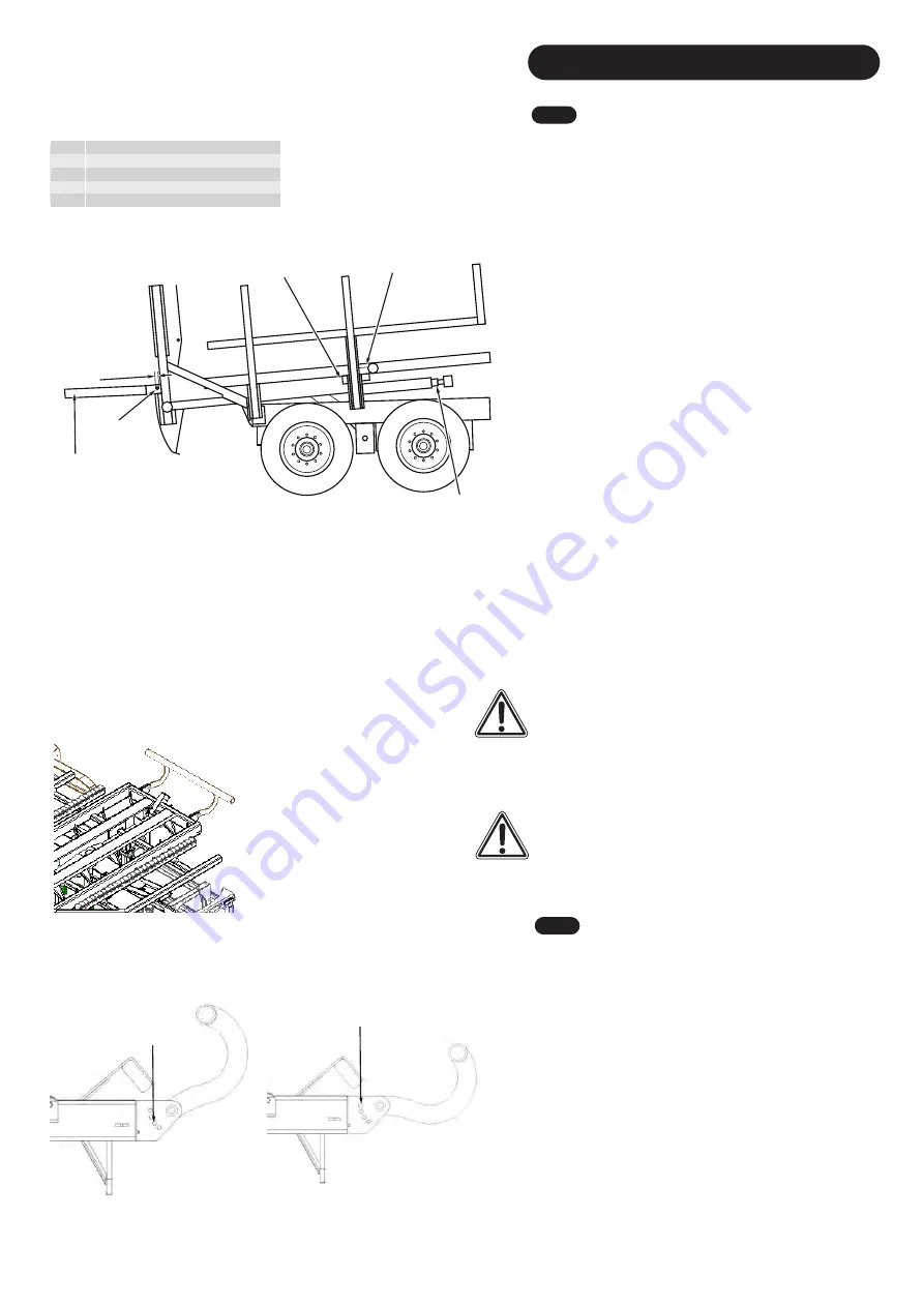
Fork Cable Adjustments
The cables should be adjusted as they leave the factory and
are unlikely to need any further attention. However, if a
cable is damaged then it will require replacement. Over time
the cables may stretch if exposed to considerable force. If
so, follow instructions below to re-adjust them.
See Fig. 8
8
1. Position the forks to the front of the trailer so the pulley
beam trolley is against the front platform beam. If the pulley
beam trolleys are not touching the front platform beam, the
fork cables may need to be released and re-adjusted. This
will push the forks against their desired sensor. If the sensor
is made when the forks are forward, the fork cable does not
need adjusting.
2. Adjust the cables by adjusting the Rigging Screw that is
located on by the center of the platform. This will push the
forks against its sensor plate, when the sensor is made, the
forks are correctly adjusted.
1
20.00
to
50.00 mm
2
3
4
5
Fig. 8
8
1
Centre clamp Beam
2
Pulley Beam
3
3 Stage Cylinder (Forks Forward)
4
Fork Pivot
5
Fork Assembly
Note
: Make sure the alignment is correct between the
sensor and the trigger plate, reference
Section
Adjustments 6.
8
.
Note
: Make sure small adjustments are made at a time to
increase accuracy of adjustments. After each small
adjustments, pressure 'Forks Forward' to put pressure back
in the system to ensure you have correctly
adjusted them.
CAUTION
:
Ensure that the 1/4" hydraulic hose which runs
parallel to the metal tension cable is longer then the cable
as this could cause damage to the machine or other. Big
Bale Co South Ltd, will NOT take responsibility for miss
adjustments. Contact Big Bale Co South Ltd for more in
depth detail for adjustments.
CAUTION
:
The 'Forks' are used for every load and can NOT
be bolted down to the platform.
6.
3
Turntable Bale Stop
The turntable has an adjustable stop (
Fig. 8
9
), this is for
different width of bales. See below for advised hole
positioning. Use other holes for fine tuning.
Hole 2 (
Fig.
90
): With Bales that have a width of
1200mm or 800mm.
Hole 4 (
Fig. 9
1
): With Bales that have a width of
1300mm (Rolled Hesst
ons)
.
Fig. 8
9
Fig. 9
1
Fig.
90
Hole 2
Hole 4
25
Содержание Transtacker 4100
Страница 61: ...58...
Страница 62: ...59...
Страница 63: ...11 0 Hydraulic Systems 11 4 Valve Block Schematic Fig 168 60...
Страница 67: ...13 0 Maintenance 13 2 Pickup Grease Points Fig 172 64...
Страница 68: ...13 0 Maintenance 13 3 Grab Arm Grease Points Fig 173 65...
Страница 69: ...13 0 Maintenance 13 4 Turntable A Frame Grease Points Fig 174 66...
Страница 70: ...13 0 Maintenance 13 5 Side Gate Grease Points Fig 175 67...
Страница 71: ...13 0 Maintenance 13 6 Rear Clamps Grease Points Fig 176 68...
Страница 72: ...13 0 Maintenance 13 7 Chassis Grease Points Fig 177 69...
Страница 73: ...13 0 Maintenance 13 8 Platform Grease Points Fig 178 70...
Страница 74: ...13 0 Maintenance 13 9 Axle Grease Points Fig 179 71...
Страница 84: ...16 0 Operators Notes 81...
Страница 85: ...82...
Страница 86: ...83...
Страница 87: ...84...