


6.0
Adjustments
6.
1
3
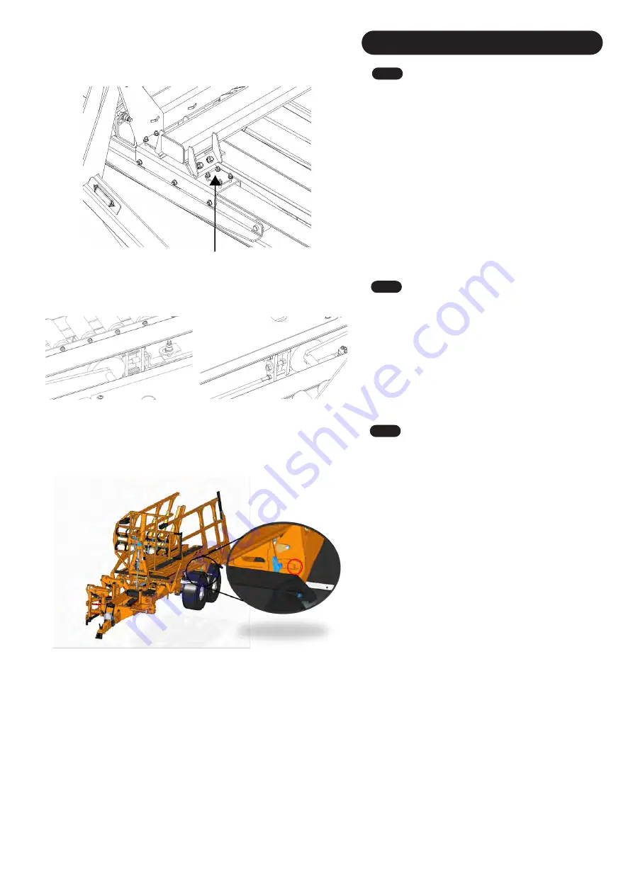
Pulley Beam Trolley Wear Pads
Fig.
1
30
Adjustable Nylons
The Pulley Beam Trolleys have X4 adjustable nylons which
allow you to keep the trolley tight to the platform and to take
out any 'Slop' that occurs. These are located on the Pulley
Beam Trollies (
Fig. 130
).
When you are adjusting these nylons, when tightening them
you should be able to move the plates on top. If you can't,
then you have overtightened the nylons.
Make sure when adjusting these plates, each M8 nut should
have an even pressure over the plate.
Note:
Ensure you do NOT over tighten these plates as this
can affect the Forks forward and will restrict the forward
movement and speed.
6.
1
4
Fork Trolley Stops
Each Fork trolley has X2 stops at its most front wards
position. X1 stop is sprung loaded as its main job is to trip
the forks forward proximity sensor (
Fig. 13
1
). On the other
side of the fork trolley there is an adjustable stop (
Fig. 13
2
).
This stop is to help keep the trolley aligned within the
platform so when the forks are to raise, they don't get
trapped up the platform. Adjust this stop in small
increments, making sure that the other side where the
proximity sensor is, still is triggering the sensor.
Fig.
1
3
1
Fig.
1
3
2
6.
1
5
Removal of Side Gate Safety Pins
The Transtacker has 2 pin holes, one is the transport
position and one is the working position. When the
Transtacker is delivered, the pin will be in the transport
position (highlighted by red circle in
Fig. 133
). When you
arrive to the field to start loading, you will need to move the
pin from the transport position into the working position (as
shown by the location of the blue pin in
Fig. 133
). As above,
the pin will only need to be completely removed when
wanting to stack side by side.
NOTE
: To prevent the pin falling out of position during the
tipping of the trailer, it needs to be inserted from the front to
the rear.
NOTE
: When traveling on the road, the side gate pins
MUST be inserted into the transport position when the
machine is empty. When the Transtacker is loaded, the pin
MUST be inserted into the working position. Any
consequences caused by the pins not being in either of the
side gate positions are the operator’s responsibility.
Fig.
1
3
3
33
Содержание Transtacker 4100
Страница 61: ...58...
Страница 62: ...59...
Страница 63: ...11 0 Hydraulic Systems 11 4 Valve Block Schematic Fig 168 60...
Страница 67: ...13 0 Maintenance 13 2 Pickup Grease Points Fig 172 64...
Страница 68: ...13 0 Maintenance 13 3 Grab Arm Grease Points Fig 173 65...
Страница 69: ...13 0 Maintenance 13 4 Turntable A Frame Grease Points Fig 174 66...
Страница 70: ...13 0 Maintenance 13 5 Side Gate Grease Points Fig 175 67...
Страница 71: ...13 0 Maintenance 13 6 Rear Clamps Grease Points Fig 176 68...
Страница 72: ...13 0 Maintenance 13 7 Chassis Grease Points Fig 177 69...
Страница 73: ...13 0 Maintenance 13 8 Platform Grease Points Fig 178 70...
Страница 74: ...13 0 Maintenance 13 9 Axle Grease Points Fig 179 71...
Страница 84: ...16 0 Operators Notes 81...
Страница 85: ...82...
Страница 86: ...83...
Страница 87: ...84...