INSTALLATION MANUAL
Logic
De
fi
nition
Default
Cross out
setting
used
Optional extras
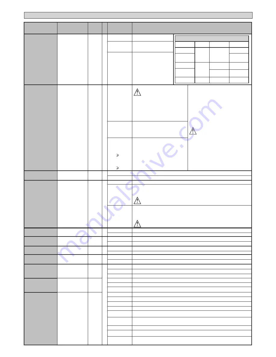
STEP-BY-STEP
MOVEMNT
Step-by-step
movement
0
0
Inputs con
fi
gured as Start E, Start I,
Ped operate with 4-step logic.
step-by-step mov.
2 STEP
3 STEP
4 STEP
CLOSED
OPENS
OPENS
OPENS
DURING
CLOSING
STOPS
OPEN
CLOSES
CLOSES
CLOSES
DURING
OPENING
STOP + TCA STOP + TCA
AFTER STOP
OPENS
OPENS
OPENS
1
Inputs con
fi
gured as Start E, Start I,
Ped operate with 3-step logic. Pulse
during closing reverses movement.
2
Inputs con
fi
gured as Start E, Start
I, Ped operate with 2-step logic.
Movement reverses with each pulse.
Encoder
Encoder
2
0
Operation with encoder disabled
WARNING
This setting fully disables the anti-crush safety
device, with serious safety risks.
Install active safety edges on closing and opening or
switch to deadman operation. (see Deadman logic)
The slowing down spaces are an estimate made
through the gate travel time.
For greater precision on the slowing down point,
set encoder = 1 or 2.
WARNING: Check that the force of impact measured at
the points provided for by standard EN 12445 is lower
than the value laid down by standard EN 12453.
WARNING: Setting sensitivity incorrectly can
result in damage to property and injury to people
and animals.
1
Operation with encoder used as position sensor for
acquiring slow-down distances. - Gate detection
locked out. Manual setting of “opening force”, “clo-
sing force”, “opening slow-down force” and “closing
slow-down force” parameters.
2
LEO B CBB DL2 3
120 F02
(
only for sw ver-
sions 7.08)
LEO B CBB DL2 3 120
F02 PHOT USA16
(
only for sw ver-
sions 8.08)
Automatic mode with encoder: slow-down and
obstacle detection performed by means of enco-
der. Adjustment of obstacle detection sensitivity
(opening force, closing force, opening slow-down
force, closing slow-down force parameters) (de-
fault setting).
PRE-ALARM
Pre-alarm
0
0
The
fl
ashing light comes on at the same time as the motor(s) start.
1
The
fl
ashing light comes on approx. 3 seconds before the motor(s) start.
HOLD-TO-RUN
Deadman
0
0
Pulse operation.
1
Deadman mode.
Input 61 is con
fi
gured as OPEN UP.
Input 62 is con
fi
gured as CLOSE UP.
Operation continues as long as the OPEN UP or CLOSE UP keys are held down.
WARNING: safety devices are not enabled.
2
Emergency Deadman mode. Usually pulse operation.
If the board fails the safety device tests (photocell or safety edge, Er0x) 3 times in a row, Deadman mode is
enabled which will stay active for 1 minute after the OPEN UP - CLOSE UP keys are released.
Input 61 is con
fi
gured as OPEN UP.
Input 62 is con
fi
gured as CLOSE UP.
WARNING: with the device set to Emergency Deadman mode, safety devices are not enabled.
IBL OPEN
Block pulses du-
ring opening
0
0
Pulse from inputs con
fi
gured as Start E, Start I, Ped has e
ff
ect during opening.
1
Pulse from inputs con
fi
gured as Start E, Start I, Ped has no e
ff
ect during opening.
IBL TCA
Block pulses
during TCA
0
0
Pulse from inputs con
fi
gured as Start E, Start I, Ped has e
ff
ect during TCA pause.
1
Pulse from inputs con
fi
gured as Start E, Start I, Ped has no e
ff
ect during TCA pause.
IBL CLOSE
Block pulses
during closing
0
0
Pulse from inputs con
fi
gured as Start E, Start I, Ped has e
ff
ect during closing.
1
Pulse from inputs con
fi
gured as Start E, Start I, Ped has no e
ff
ect during closing.
OPEN IN OTHER
DIRECT.
Open in other
direction
0
0
Standard operating mode (Fig.G Rif. 1).
1
Opens in other direction to standard operating mode (Fig. G Rif.2)
SAFE 1
Con
fi
guration
of safety input
SAFE 1.
72
0
0
Input con
fi
gured as Phot (photocell).
1
Input con
fi
gured as Phot test (tested photocell).
2
Input con
fi
gured as Phot op (photocell active during opening only).
SAFE 2
Con
fi
guration
of safety input
SAFE 2.
74
6
3
Input con
fi
gured as Phot op test (tested photocell active during opening only).
4
Input con
fi
gured as Phot cl (photocell active during closing only).
5
Input con
fi
gured as Phot cl test (tested photocell active during closing only).
SAFE 3
Con
fi
guration
of safety input
SAFE 3.
77
2
6
Input con
fi
gured as Bar, safety edge.
7
Input con
fi
gured as Bar, tested safety edge.
8
Input con
fi
gured as Bar 8k2
(Inactive on SAFE 3).
9*
Input con
fi
gured as Bar OP, safety edge with inversion active only while opening. If while closing, the movement stops.
10*
Input con
fi
gured as Bar OP TEST, safety edge tested with inversion active only while opening. If while closing,
the movement stops.
11*
Input con
fi
gured as Bar OP 8k2, safety edge with inversion active only while opening. If while closing, the
movement stops.
(Inactive on SAFE 3).
12*
Input con
fi
gured as Bar CL, safety edge with inversion active only while closing. If while opening, the movement stops.
13*
Input con
fi
gured as Bar CL TEST, safety edge tested with inversion active only while closing. If while opening,
the movement stops.
14*
Input con
fi
gured as Bar CL 8k2, safety edge with inversion active only while closing. If while opening, the
movement stops.
(Inactive on SAFE 3).
38 -
LEO B CBB DL2 3 230 L02-LEO B CBB DL2 3 120 F02-
LEO B CBB DL2 3 120 F02 PHOT USA16
D812916 00100_02


