128
9440300990 Rev J
BESTCOMS
Plus
®
Software
DECS-250
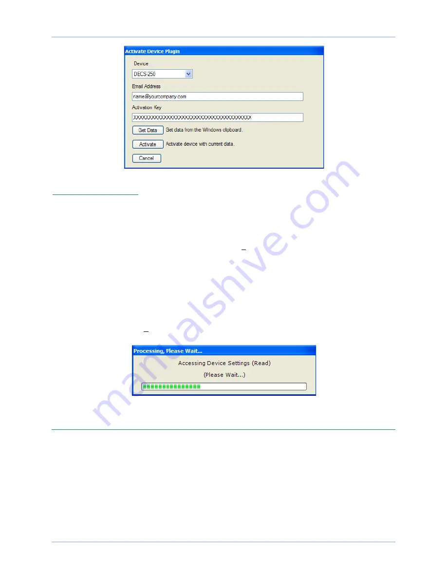
Figure 116. Activate Device Plugin Screen
Entering an Activation Key
Select DECS-250 from the
Device
pull-down menu. Enter your
Email Address
and
Activation Key
provided by Basler Electric. If you received an email containing the
Activation Key
, you can select all of
the text in the email and copy it to the Windows clipboard using normal Windows techniques. The
Get
Data
button extracts the
Device, Email Address,
and
Activation Key
from the Windows clipboard and
pastes it into the appropriate fields. Click the
Activate
button to continue. The
Activate Device Plugin
screen is also found by selecting
Activate Device
from the
Tools
pull-down menu of the BESTCOMS
Plus
main screen.
Establishing Communication
Communication between BESTCOMS
Plus
and the DECS-250 is established by clicking the
Connect
button on the
DECS-250 Connection
screen (see Figure 115) or by clicking the
Connect
button on the
lower menu bar of the main BESTCOMS
Plus
screen (Figure 111). If you receive an “Unable to Connect
to Device” error message, verify that communications are configured properly. Only one Ethernet
connection is allowed at one time. Download all settings and logic from the relay by selecting
Download
Settings and Logic
from the
Communication
pull-down menu. BESTCOMS
Plus
will read all settings and
logic from the DECS-250 and load them into BESTCOMS
Plus
memory. See Figure 117.
Figure 117. Processing, Please Wait…
Menu Bars
The menu bars are located near the top of the BESTCOMS
Plus
®
screen (see Figure 111). The upper
menu bar has five pull-down menus. With the upper menu bar, it is possible to manage settings files,
configure communication settings, upload and download settings and security files, and compare settings
files. The lower menu bar consists of clickable icons. The lower menu bar is used to change
BESTCOMS
Plus
views, open a settings file, connect/disconnect, preview metering printout, switch to live
mode, and send settings after a change is made when not in live mode.
Upper Menu Bar (BESTCOMSPlus
®
Shell)
Upper menu bar functions are listed and described in Table 9.
Содержание DECS-250
Страница 2: ......
Страница 6: ...iv 9440300990 Rev J Revision History DECS 250 ...
Страница 16: ...xiv 9440300990 Rev J Contents DECS 250 ...
Страница 20: ...4 9440300990 Rev J Introduction DECS 250 ...
Страница 28: ...12 9440300990 Rev J Power Stage DECS 250 ...
Страница 32: ...16 9440300990 Rev J Voltage and Current Sensing DECS 250 ...
Страница 40: ...24 9440300990 Rev J Synchronizer DECS 250 ...
Страница 52: ...36 9440300990 Rev J Auxiliary Control DECS 250 ...
Страница 56: ...40 9440300990 Rev J Contact Inputs and Outputs DECS 250 ...
Страница 84: ...68 9440300990 Rev J Limiters DECS 250 ...
Страница 108: ...92 9440300990 Rev J Power System Stabilizer DECS 250 Figure 85 PSS Function Blocks and Software Switches ...
Страница 114: ...98 9440300990 Rev J Power System Stabilizer DECS 250 Figure 96 PSS Parameter Settings ...
Страница 124: ...108 9440300990 Rev J Stability Tuning DECS 250 ...
Страница 126: ...110 9440300990 Rev J Mounting DECS 250 Figure 103 Overall and Projection Mounting Dimensions ...
Страница 127: ...9440300990 Rev J 111 DECS 250 Mounting Figure 104 DECS 250 Escutcheon Plate Dimensions ...
Страница 128: ...112 9440300990 Rev J Mounting DECS 250 Figure 105 Panel Cutting and Drilling Dimensions for DECS 250 Panel Mounting ...
Страница 198: ...182 9440300990 Rev J Timekeeping DECS 250 ...
Страница 210: ...194 9440300990 Rev J CAN Communication DECS 250 ...
Страница 304: ...288 9440300990 Rev J Maintenance DECS 250 ...
Страница 316: ...300 9440300990 Rev J Specifications DECS 250 ...
Страница 334: ...318 9440300990 Rev J Analog Expansion Module DECS 250 ...
Страница 341: ...9440300990 Rev J 325 DECS 250 Contact Expansion Module Figure 188 CEM 2020 Input Contact and Output Contact Terminals ...
Страница 351: ......


