DL205 Analog Manual, 7th Edition Rev. D
3-13
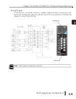
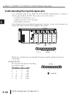
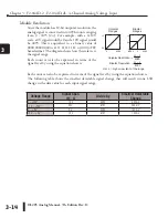
Chapter 3: F2-04AD-2, F2-04AD-2L, 4-Channel Analog Voltage Input
1
2
3
4
5
6
7
8
9
10
11
12
13
14
A
B
C
D
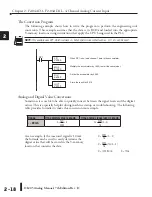
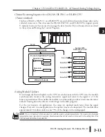
Active Channel Indicator Inputs
Two of the inputs are binary-encoded to
indicate the active channel (remember,
the V-memory bits are mapped directly to
discrete inputs). The inputs automatically
turn on and off to indicate the current
channel for each scan.
Scan X35
X34 Channel
N
Off
Off
1
N+1 Off
On 2
N+2 On
Off 3
N+3 On
On 4
N+4 Off Off 1
Module Diagnostic and Sign Inputs
The last two inputs are used for module
diagnostics.
Module Busy - The first diagnostic input
(X36 in this example) indicates a ”busy”
condition. This input will always be active
on the first PLC scan, to tell the CPU the
analog data is not valid. After the first scan,
the input usually only comes on when
extreme environmental (electrical) noise
problems are present.
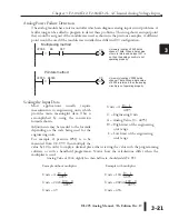
The last input (X37 in this example) is used for two purposes.
Signal Sign - When using bipolar ranges the value returned needs to be known if it is either
positive or negative. When this input is off, the value stored represents a positive analog signal
(0V or greater). If the input is on, then the value stored represents a negative input signal (less
than 0V).
Channel Failure - The last diagnostic input can also indicate an analog channel failure. For
example, if the 24VDC input power is missing or if the terminal block is loose, the module will
turn on this input point and also returns a data value of zero (remember, if this input is on and
the data value is not equal to zero, then it is just showing the sign).
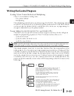
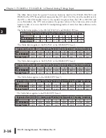
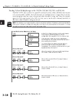
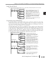
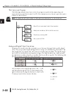
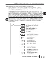
The next section, Writing the Control Program, shows how these inputs can be used in a
program.
1
2
3
4
5
6
7
8
9
10
11
12
13
14
A
b
D
MSB
LSB
X
2
0
X
3
5
X
3
4
= channel inputs
V40401
MSB
LSB
X
2
0
X
3
7
X
3
6
= Module Busy
V40401
= diagnostic and sign
Содержание DL205
Страница 1: ...DL205 Analog I O Manual Manual Number D2 ANLG M ...
Страница 2: ...Notes ...
Страница 6: ...Notes ...

