DL205 Analog Manual, 7th Edition Rev. D
2-11
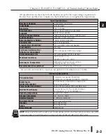
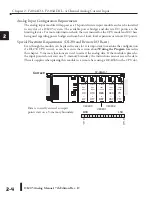
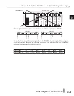
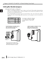
Chapter 2: F2-04AD-1, F2-04AD-1L, 4-Channel Analog Current Input
1
2
3
4
5
6
7
8
9
10
11
12
13
14
A
B
C
D
1
2
3
4
5
6
7
8
9
10
11
12
13
14
A
b
C
D
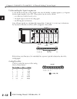
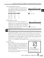
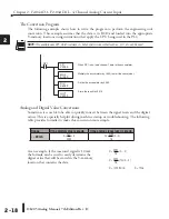
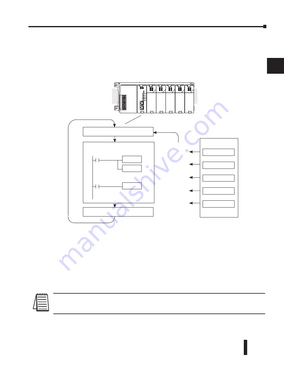
Channel Scanning Sequence for a DL240, DL250-1 or DL260 CPU
(Pointer method)
If a DL240/250-1/260 CPU is used, All four channels of input data in one scan can be
collected. This is because the DL240/250-1/260 CPU supports special V-memory locations
that are used to manage the data transfer. This is discussed in more detail in the section on
Writing the Control Program
later in this chapter.
Analog Module Updates
Even though the channel updates to the CPU are synchronous with the CPU scan, the module
asynchronously monitors the analog transmitter signal and converts the signal to a 12-bit
binary representation. This enables the module to continuously provide accurate measurements
without slowing down the discrete control logic in the RLL program.
For the vast majority of applications, the values are updated much faster than the signal
changes. However, in some applications, the update time can be important. The module takes
approximately 4 milliseconds to sense 95% of the change in the analog signal.
NOTE:
This is not the amount of time required to convert the signal to a digital representation. The conversion to the digital
representation takes only a few microseconds. Many manufacturers list the conversion time, but it is the settling time of the
filter that really determines the update time.
Read the data
Store data
Read Inputs
Execute Application Program
Scan
Write to Outputs
Ch 1, 2, 3, 4
Scan N
Scan N+1
Scan N+2
Scan N+3
Scan N+4
Ch 1, 2, 3, 4
Ch 1, 2, 3, 4
Ch 1, 2, 3, 4
Ch 1, 2, 3, 4
System With
DL240/250--1/260
CPU
Содержание DL205
Страница 1: ...DL205 Analog I O Manual Manual Number D2 ANLG M ...
Страница 2: ...Notes ...
Страница 6: ...Notes ...

