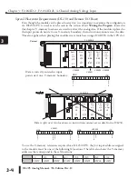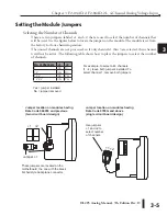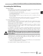
DL205 Analog Manual, 7th Edition Rev. D
3-8
Chapter 3: F2-04AD-2 , F2-04AD-2L, 4-Channel Analog Voltage Input
1
2
3
4
5
6
7
8
9
10
11
12
13
14
A
B
C
D
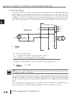
Custom Input Ranges
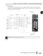
At times, there may be a need to connect a (current) transmitter with an unusual signal range.
By changing the wiring slightly and adding an external resistor to convert the current to
voltage, the module can be easily adapted to meet the specifications for a transmitter that does
not adhere to one of the standard input ranges. The following diagram shows how this can be
done. The example below only shows channel 1, but the other channels can be used as well.
NOTE:
The choice of resistor can affect the accuracy of the module. A resistor that has
±
0.1% tolerance and a
±
50 ppm
/
°
C temperature coefficient is recommended.
If a 4–20 mA signals are used and converted to voltage using this method, a broken transmitter
condition can easily be detected. For example, if using the 0–5V range and the lowest signal
for the 4–20 mA transmitter is 4mA, the lowest digital value for the signal is not 0, but instead
is 819.
If the transmitter is working properly, the smallest value would be 819 in the DL205. If the
value is less than about 750 (allowing for tolerance), then the transmitter is broken.
1
2
3
4
5
6
7
8
9
10
11
12
13
14
A
b
C
D
Current
IN +
IN --
+
--
R
Field wiring
Module internal circuitry
50 mA
Transmitter
O V
A to D
Converter
Analog
Sw
itch
CH1
CH2
CH3
CH4
24 V
0 V
DC
to
DC
Conv
er
te
r
+5 V
+15 V
0 V
--15 V
24 V
0 V
R = value of external resistor
V
max
= high limit of selected voltage range (5V or 10V)
I
max
= maximum current supplied by the transmitter
Example: current transmitter capable of 50mA, 0–10V range selected.
R = 10V R = 200
q
50mA
R = V
,
max
I
max
Содержание DL205
Страница 1: ...DL205 Analog I O Manual Manual Number D2 ANLG M ...
Страница 2: ...Notes ...
Страница 6: ...Notes ...

