DL205 Analog Manual, 7th Edition Rev. D
4-5
Chapter 4: F2-08AD-1, 8-Channel Analog Current Input
1
2
3
4
5
6
7
8
9
10
11
12
13
14
A
B
C
D
Setting the Module Jumpers
Selecting the Number of Channels
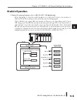
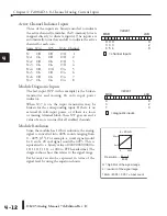
There are two jumpers, l1, +2, and +4 which are used to select the number of channels
that will be used. Use the figures below to locate the jumpers on the module. The module is set
from the factory for eight channel operation (all three jumpers installed).
The unused channels are not processed, so if only channels 1 thru 3 are selected, channels 4
through 8 will not be active. The following table shows how to use the jumpers to select the
number of channels.
1
2
3
4
5
6
7
8
9
10
11
12
13
14
A
b
C
D
+1
+2
+1 +2 +4
+4
+1+2+4
No. of Channels +1
+2 +4
1
No
No
No
1, 2
Yes
No
No
1, 2, 3
No
Yes
No
1, 2, 3, 4
Yes
Yes
No
1, 2, 3, 4, 5
No
No
Yes
1, 2, 3, 4, 5, 6
Yes
No
Yes
1, 2, 3, 4, 5, 6, 7
No
Yes
Yes
1, 2, 3, 4, 5, 6, 7, 8
Yes
Yes
Yes
For example, to select all 8-channel
operation, leave three jumpers
installed. To select channel 1, remove
(or store on a single post to prevent
losing them) all three jumpers
Jumper location on modules having
date code 0609B9 and previous
(two circuit board design)
Jumper location on modules having
date code 0709C1 and above
(single circuit board design)
These jumpers are located on the
motherboard, the one with the black
D-shell style backplane connector.
Yes = jumper installed
No = jumper removed
Содержание DL205
Страница 1: ...DL205 Analog I O Manual Manual Number D2 ANLG M ...
Страница 2: ...Notes ...
Страница 6: ...Notes ...

