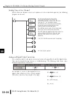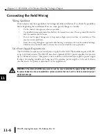
DL205 Analog Manual, 7th Edition Rev. D
10-11
Chapter 10: F2-08DA-1, 8-Channel Analog Current Output
1
2
3
4
5
6
7
8
9
10
11
12
13
14
A
B
C
D
Writing the Control Program
Calculating the Digital Value
The control program must calculate the digital
value that is sent to the analog output. Several
methods can be used to do this, but the best
method is to convert the values to engineering
units. This is accomplished by using the
formula shown.
Adjustments may have to be made to the
formula depending on the scale of the engi-
neering units.
Consider the following example which controls pressure from 0.0–99.9 PSI. Using the
formula will calculate the digital value to be sent to the analog output. The example shows
the conversion required to yield 49.4 PSI. The multiplier of 10 is used because the decimal
portion of 49.4 cannot be loaded in the program, so it is shifted right one decimal place to
make a usable value of 494.
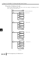
The Conversion Program
The example program shows how to write the program to perform the engineering unit
conversion. This example assumes that a BCD value has been stored in V2300 and V2301 for
channels 1 and 2 respectively.
NOTE:
The DL205 has many instructions available so that math operations can simply be performed using BCD format.
Do the math in BCD, then convert to binary before writing to the module output.
1
2
3
4
5
6
7
8
9
10
11
12
13
14
A
b
C
D
For 0–4095 output format
A = U 4095
H – L
A = Analog Value (0–4095)
U = Engineering Units
H = High limit of the engineering
unit range
L = Low limit of the engineering
unit range
The LD instruction loads the engineering units used with channel 1 into
the accumulator. This example assumes the numbers are BCD. Since
SP1 is used, this rung automatically executes on every scan. You could
also use an X, C, etc. permissive contact.
LD
V2300
SP1
MUL
K4095
DIV
K1000
Multiply the accumulator by 4095 (to start the conversion).
Divide the accumulator by 1000 (because we used a multiplier of 10,
we have to use 1000 instead of 100).
OUT
V2000
Store the BCD result in V2000 (the actual steps required to send the
data are shown later).
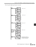
The LD instruction loads the engineering units used with channel 2 into
the accumulator. This example assumes the numbers are BCD. Since
SP1 is used, this rung automatically executes on every scan. You could
also use an X, C, etc. permissive contact.
LD
V2301
SP1
MUL
K4095
DIV
K1000
Multiply the accumulator by 4095 (to start the conversion).
Divide the accumulator by 1000 (because we used a multiplier of 10,
we have to use 1000 instead of 100).
OUT
V2001
Store the BCD result in V2001 (the actual steps required to send the
data are shown later).
A = 10U 4095 A = 494 4095 A–2023
10 (H–L) 1000–0)
Содержание DL205
Страница 1: ...DL205 Analog I O Manual Manual Number D2 ANLG M ...
Страница 2: ...Notes ...
Страница 6: ...Notes ...

