DL205 Analog I/O Manual, 7th Edition Rev. D
1-3
Chapter 1: Getting Started
1
2
3
4
5
6
7
8
9
10
11
12
13
14
A
B
C
D
Conventions Used
When the “notepad” icon is in the left–hand margin, the paragraph to its immediate right will
be a special note.
The word
NOTE
in boldface will mark the beginning of the text.
When the “exclamation mark” icon is in the left–hand margin, the paragraph to its immediate
right will be a warning. This information could prevent injury, loss of property, or even death
(in extreme cases).
The word
WARNING
in boldface will mark the beginning of the text which will also be in
boldface..
Key Topics for Each Chapter
The beginning of each chapter will list the key topics
that can be found in that chapter.
Physical Characteristics
The DL205 Analog Modules provide many features that make the modules easy to use. With
the exception of the thermocouple module, the terminal blocks are removable, which makes
wiring a simple task. All of the DL205 analog modules have normal screw terminal connectors.
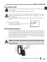
Access the module terminals by removing the front cover (not shown). To remove the front
cover, press the tab on the lower front corner of the cover. For ease of removal, the terminal
blocks have squeeze tabs on the top and bottom. To remove a terminal block, press the tabs and
pull the terminal block away from the module.
WARNING: For some modules, field device power may still be present on the terminal block even though
the PLC system is turned off. To minimize the risk of electrical shock, check all field device power before
you remove the connector.
1
2
3
4
5
6
7
8
9
10
11
12
13
14
A
b
C
D
Getting Started
C
HAPTER
1
In This Chapter...
.................................................................1-2
...........................................................................1-4
Specifications
General Information
Press tabs
to remove
terminal
block.
Содержание DL205
Страница 1: ...DL205 Analog I O Manual Manual Number D2 ANLG M ...
Страница 2: ...Notes ...
Страница 6: ...Notes ...

