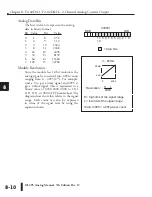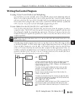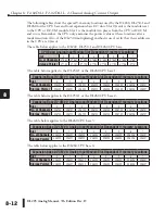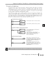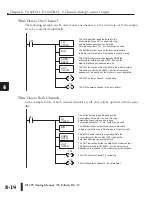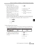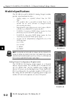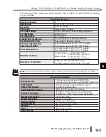
DL205 Analog Manual, 7th Edition Rev. D
8-6
Chapter 8: F2-02DA-1, F2-02DA-1L, 2-Channel Analog Current Output
1
2
3
4
5
6
7
8
9
10
11
12
13
14
A
b
C
D
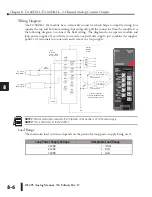
Wiring Diagram
The F2-02DA-1 (L) module has a removable connector which helps to simplify wiring. Just
squeeze the top and bottom retaining clips and gently pull the connector from the module. Use
the following diagram to connect the field wiring. The diagram shows separate module and
loop power supplies. If you desire to use only one field-side supply, just combine the supplies’
positive (+) terminals into one node and remove the loop supply.
NOTE 1:
Shields should be connected to the 0V terminal of the module or 0V of the power supply.
NOTE 2:
This is 60mA only for the F2-02DA-1.
Load Range
The maximum load resistance depends on the particular loop power supply being used.
1
2
3
4
5
6
7
8
9
10
11
12
13
14
A
b
C
D
OV
+
--
12 VDC
See
0VDC
+12VDC
N/C
N/C
N/C
N/C
NOTE 1
70mA + 20mA
for each loop
CH1--
CH2--
CH1+
CH2+
Current sinking
Ch 1
Current sinking
Ch 2
D
C
to
D
C
C
on
ve
rte
r
+5V
+15V
0V
--15V
D to A
Converter
D to A
Converter
Ch 1 load
250Ω typical
Ch 2 load
250Ω typical
Internal
Module
Wiring
Transient protected
precision digital to analog
converter output circuits
+12V
CH1+
CH2+
NC
NC
0V
CH1–
CH2–
NC
NC
F2-02DA-1L
OUT
ANALOG
2CH
F2-02DA-1L
10-15VDC
70mA
ANALOG OUT
4-20mA
See
NOTE 2
Loop Power Supply Voltage
Acceptable Load Range
30VDC
0 – 1200
q
24VDC
0 – 910
q
18VDC
0 – 620
q
Содержание DL205
Страница 1: ...DL205 Analog I O Manual Manual Number D2 ANLG M ...
Страница 2: ...Notes ...
Страница 6: ...Notes ...


