DL205 Analog Manual, 7th Edition Rev. D
9-13
Chapter 9: F2-02DA-2, F2-02DA-2L, 2-Channel Analog Voltage Output
1
2
3
4
5
6
7
8
9
10
11
12
13
14
A
B
C
D
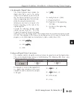
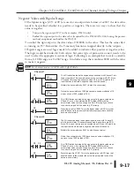
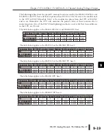
Analog Data Bits
The first twelve bits represent the analog
data in binary format.
Bit Value
Bit Value
0
1
6 64
1
2
7 128
2
4 8 256
3
8 9 512
4 16 10 1024
5 32 11 2048
Signal Sign Output
The last output can be used to select the
signal sign (+ or -) for bipolar ranges. By
controlling this output, positive and
negative data values can be easily selected.
Programming examples in the next section,
Writing the Control Program
, will show
how to make sign selection part of the
program.
Bipolar Output Data
If an output channel is configured for an
output format of 0 – 2047, the maximum
valid value for the lower 12 bits is 2047. This
means that bit 11 (bit position 12) must
always be 0 (zero).
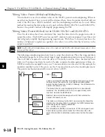
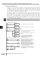
WARNING: If the data value exceeds 2047, bit 11 becomes a ”1”, and the other eleven bits start over
at ”00000000000”. At this point the module’s channel output voltage also goes back to the bottom of
its range and begins to increase again. The RLL program will be expecting a maximum output, but it
will be minimum instead. This can have serious consequences in some applications, and may result in
personal injury or damage to equipment. Therefore, in standard bipolar ranges (or whenever the output
format is ±2047 in general), be sure that the RLL program does not create numbers with absolute values
greater than 2047.
1
2
3
4
5
6
7
8
9
10
11
12
13
14
A
b
C
D
V40501
B
S
L
B
S
M
0
1
1
1
0
9 8 7 6 5 4 3 2 1
= data bits
= signal sign output
Y
3
7
V40501
B
S
L
B
S
M
Y
2
0
V40501
B
S
L
B
S
M
0
1
1
1
0
9 8 7 6 5 4 3 2 1
= data bits
0
Bit 11 must be 0 for output
format 2047.
Содержание DL205
Страница 1: ...DL205 Analog I O Manual Manual Number D2 ANLG M ...
Страница 2: ...Notes ...
Страница 6: ...Notes ...

