92
NOTE: When replacing the inner water pump seals,
use the recommended Water Pump Bearing and Seal
Tool Kit only.
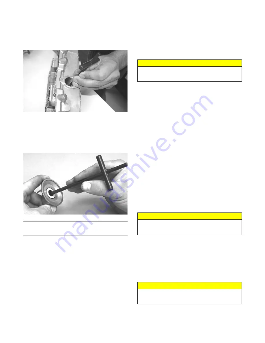
27. Place the crankcase on the bench with the water
pump side down. Using the long seal driver, drive the
mechanical water pump seal from the crankcase.
FC036
28. Using a pair of snap ring pliers, remove the snap ring
securing the inner seal in the crankcase.
29. Using the hooked end of the tool, pull the inner seal
free of the crankcase.
30. Using the hooked end of the tool, pry the seal ring
from the backside of the water pump impeller.
AN327D
Cleaning and Inspecting
CYLINDER HEAD
1. Using a non-metallic carbon removal tool, remove
any carbon buildup from the combustion chambers
being careful not to nick, scrape, or damage the com-
bustion chambers or the sealing surfaces.
2. Inspect the spark-plug holes for any damaged
threads.
NOTE: If warpage is suspected, have a qualified
machine shop inspect and repair if necessary.
3. Place the cylinder head on a Surface Plate covered
with #400 grit wet-or-dry sandpaper. Using light
pressure, move each cylinder head in a figure eight
motion. Inspect the sealing surface for any indication
of high spots. A high spot can be noted by a bright
metallic finish. Correct any high spots before assem-
bly by continuing to move the cylinder head in a fig-
ure eight motion until a uniform bright metallic
finish is attained.
CYLINDERS
1. Using a non-metallic carbon removal tool, remove
carbon buildup from the exhaust ports.
2. Wash the cylinders in parts-cleaning solvent.
3. Inspect the cylinders for pitting, scoring, scuffing,
and corrosion. If marks are found, repair the surface
with the Ball Hone and honing oil.
NOTE: To produce the proper 45° crosshatch pat-
tern, maintain a low drill RPM. If honing oil is not
available, use a lightweight, petroleum-based oil.
Thoroughly clean the cylinders after honing using
detergent soap and hot water and dry with com-
pressed air; then immediately apply oil to the cylinder
bores. If a bore is severely damaged or gouged, the
cylinder must be replaced.
4. Place the head surface of each cylinder on the sur-
face plate covered with #400 grit wet-or-dry sandpa-
per. Using light pressure, move each cylinder in a
figure eight motion. Inspect the surface for any indi-
cation of high spots. A high spot can be noted by a
bright metallic finish. Correct any high spots before
assembly by continuing to move the cylinder in a fig-
ure eight motion until a uniform bright metallic fin-
ish is attained.
PISTON ASSEMBLY
1. Using a non-metallic carbon removal tool, remove
the carbon buildup from the dome of each piston.
2. Snap an old piston ring into two pieces; then grind
the end of the old ring to a 45° angle and to a sharp
edge. Using the sharpened ring as a tool, clean car-
bon from the ring-grooves. Be sure to position the
ring with its tapered side up.
3. Inspect each piston for cracks in the piston pin and
skirt areas.
CAUTION
Water or parts-cleaning solvent must be used in con-
junction with the wet-or-dry sandpaper or damage to
the sealing surface may result.
CAUTION
Water or parts-cleaning solvent must be used in con-
junction with the wet-or-dry sandpaper or damage to
the sealing surface may result.
CAUTION
Improper cleaning of the ring-grooves by the use of the
wrong type of ring-groove cleaner will result in severe
damage to the piston.
Содержание M 8000
Страница 1: ...www arcticcat com SERVICE MANUAL www arcticcat com...
Страница 42: ...41 500cc_2A_15...
Страница 50: ...49 600_14_2...
Страница 58: ...57 800_12_2...
Страница 155: ...154 Troubleshooting Servomotor SERVO1A16...
Страница 156: ...155 SERVO2rv16...
Страница 193: ...192 0747 414 M 141 High Country Models...
Страница 209: ...208 NOTES...
Страница 210: ...Printed in U S A Trademarks of Arctic Cat Inc Thief River Falls MN 56701 p n 2260 847...


