84
CWI-078A
23. Apply oil to the connecting-rod small end bearings;
then install the small-end bearings.
24. Place each piston over the connecting rod so the indi-
cator arrow on each piston will point toward the
exhaust ports; then secure with an oiled piston pin.
NOTE: The indicator arrow is found on the piston
dome.
25. Install the new circlips so the open end is directed
either up or down.
26. Rotate each piston ring until the ring ends are prop-
erly positioned on either side of the ring keeper; then
apply oil to the piston assemblies and cylinder bores.
CWI-063
27. In turn on each cylinder, place a piston holder (or
suitable substitute) beneath the piston skirt and
square the piston in respect to the crankcase; then
using a ring compressor or fingers, compress the
rings and slide the cylinder over the piston. Remove
the piston holder and seat the cylinder firmly onto
the crankcase.
NOTE: The cylinders should slide on easily. DO
NOT force the pistons into the cylinders.
28. Install each cylinder with the eight existing nuts;
then secure the cylinders by tightening the cylinder
base nuts to 15 ft-lb then to 32 ft-lb in a crisscross
pattern.
29. Install the cylinder O-rings (lightly coated with oil)
on the top of each cylinder making sure they are cor-
rectly positioned in the grooves.
CWI-010
30. Place new O-rings (lightly coated with oil) onto each
of the head cap screws. Place four of these cap
screws (from opposite end of each other) into the
cylinder head. Thread the spark plugs in part way;
then while holding the head above the cylinder, care-
fully start and finger-tighten all four cap screws
while observing the cylinder O-rings to make sure
they remain in position. Slowly place the head into
position on top of the O-rings.
NOTE: To install the remaining cap screws, the
spark plugs must be removed.
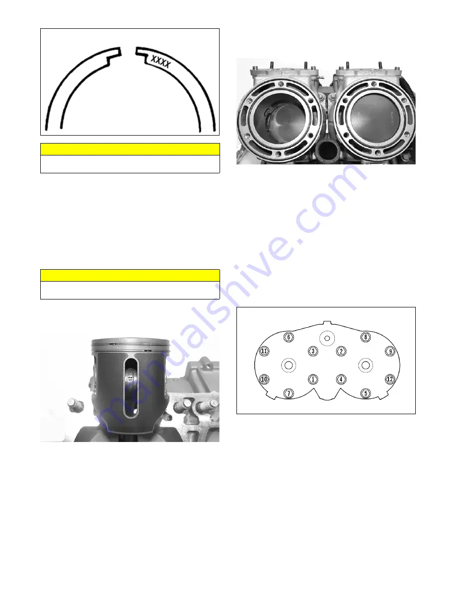
31. Start and finger-tighten the cap screws being very
careful not to move the cylinder head; then tighten
the cap screws in two steps to 13 ft-lb then 25 ft-lb
using the pattern shown.
0747-890
NOTE: At this point, install the spark plugs; then
install the knock sensor. Tighten the sensor to 18 ft-lb.
32. Install the coolant inlet hose to the cylinder head and
water pump; then secure using the clamp.
33. Install the fuel rail assembly into the back of the cyl-
inders making sure the gaskets are in place; then
secure the rail using new nylon nuts. Tighten to 102
in.-lb.
CAUTION
Incorrect installation of the piston rings will result in
engine damage.
CAUTION
Make sure the circlips are firmly seated before continu-
ing with assembly.
Содержание M 8000
Страница 1: ...www arcticcat com SERVICE MANUAL www arcticcat com...
Страница 42: ...41 500cc_2A_15...
Страница 50: ...49 600_14_2...
Страница 58: ...57 800_12_2...
Страница 155: ...154 Troubleshooting Servomotor SERVO1A16...
Страница 156: ...155 SERVO2rv16...
Страница 193: ...192 0747 414 M 141 High Country Models...
Страница 209: ...208 NOTES...
Страница 210: ...Printed in U S A Trademarks of Arctic Cat Inc Thief River Falls MN 56701 p n 2260 847...


