


CV10 Touch Panel Accessories
24
10" Modero Touch Panels
Step 4: Close and Resecure the NXT Panel Enclosure
1.
In a single motion
, gently slide the rear Tilt Bracket cover plate back over the tilt mechanism (
located
below the LCD
) and (
while angling the housing downwards
) slide the outer housing below the Tilt
Bracket and towards the LCD (at a downward angle).
2.
Locate the two screw holes at either sides of the front speaker grill and then use a grounded
Phillips-head screwdriver to both insert and secure the two Tilt Bracket Screws (FIG. 19). This procedure
resecures the rear Tilt Bracket cover plate (
with the AMX logo and Hinge brackets
).
3.
Press the outer housing forwards until it is aligned over the outer housing installation holes. Once
installed and secured, the tilt bracket prevents any further movement (FIG. 20).
4.
Gently press down on the housing (toward the base) until it is securely positioned over the circuit board
and base.
5.
While holding the circuit board cover in place, turn the panel back over until the LCD lies facedown on a
soft cloth and the under-side of the base is exposed.
6.
Insert and secure the four Housing Screws (using a grounded Phillips-head screwdriver) in their
respective locations, as shown in FIG. 18 on page 20.
7.
Replace any adhesive plastic "feet" that might have been removed during the removal process of the outer
housing.
These "feet" must be placed back onto their original locations so they can fit into their provided
openings on the Battery Base.
8.
Grasp both the LCD and housing and then rotate the entire unit back onto a flat surface.
9.
Insert all connectors and apply power.
Installation and Upgrade of the Internal NXD Components
Upgrading the cards within the WallMount panel involves removing the rear plastic outer housing (back box),
removing the existing card, replacing it with the 802.11g upgrade, and then placing the back box back onto the
NXD panel, as described in the following sections.
These panels do not come factory installed with the NXA-WC802.11GCF wireless interface card. This card
must be ordered separately from AMX as part of the 802.11g upgrade kit (
FG2255-07
).
Step 1: Remove the existing NXD Outer Housing
1.
Carefully detach all connectors from the side of the touch panel and remove the Faceplate from the front
of the panel.
2.
Place the LCD facedown on a soft cloth to expose the under-side of the unit (FIG. 24). This step helps
prevent scratching of the LCD
.
3.
Firmly press down on both connector overlay release latches (located in front of the connectors).
Pressing
down releases the connector overlay from atop the connectors.
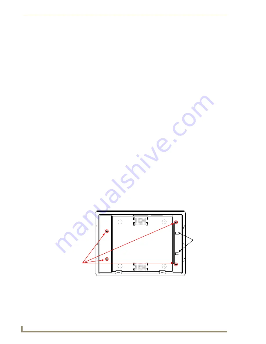
FIG. 24
Location of the attachment screws and connector overlay release latches on an NXD back box
Unscrew these
four pan-head
Two (2) connector
housing screws
to remove the
back box
overlay release
(2 per side)
latches
Содержание modero NXD-CV10
Страница 1: ...Operation Reference Guide Touch Panels NXT D CV10 10 Modero Touch Panel Last Revised 7 2 2012 ...
Страница 44: ...CV10 Touch Panel Accessories 32 10 Modero Touch Panels ...
Страница 58: ...Installation 46 10 Modero Touch Panels ...
Страница 88: ...Configuring Communication 76 10 Modero Touch Panels ...
Страница 98: ...Upgrading Modero Firmware 86 10 Modero Touch Panels ...
Страница 192: ...Appendix A 180 10 Modero Touch Panels ...
Страница 206: ...Troubleshooting 194 10 Modero Touch Panels ...
Страница 207: ...Appendix 195 10 Modero Touch Panels ...


