


Installation Procedures: 12" and 15" Panels
45
12” and 15” Modero Touch Panels
10.
Reinstall the magnetic faceplate (
A
in
FIG. 45) back onto the main NXD unit (
B
in
FIG. 45).
Make sure
to align the Microphone, Light, and PIR Motion sensor locations to their respective openings on the front
bezel/faceplate.
11.
Connect the terminal RJ-45, Ethernet, and any optional audio/video wiring to their respective locations on
either the NXA-AVB Breakout Box, Ethernet port, or NetLinx Master.
12.
Reconnect the terminal power connector on the PSN and apply power.
Installing an NXD into an (optional) Rack Mount Kit (NXA-RK12 or NXA-RK15)
1.
Remove the magnetic faceplate/bezel from the main NXD unit by gripping the faceplate and pulling with
gentle outward force.
2.
Thread the incoming RJ-45, Ethernet, and any optional audio/video wiring through the opening in the
equipment rack (from their terminal locations). Refer to the
Wiring Guidelines for the 12" and 15"
Panels
section on page 47 for pinout descriptions. Leave enough slack to accommodate any re-
positioning of the panel.
3.
Connect all data and power wiring connectors to their corresponding locations along the side of the (un-
powered) NXD touch panel.
Verify the terminal end of the power cable is not connected to a power supply before plugging in the 2-pin
power connector.
4.
Test the incoming wiring by connecting the panel connections to their terminal locations and applying
power. Verify the panel is receiving power and functioning properly to prevent repetition of the
installation.
5.
Disconnect the terminal end of the power cable from the connected power supply.
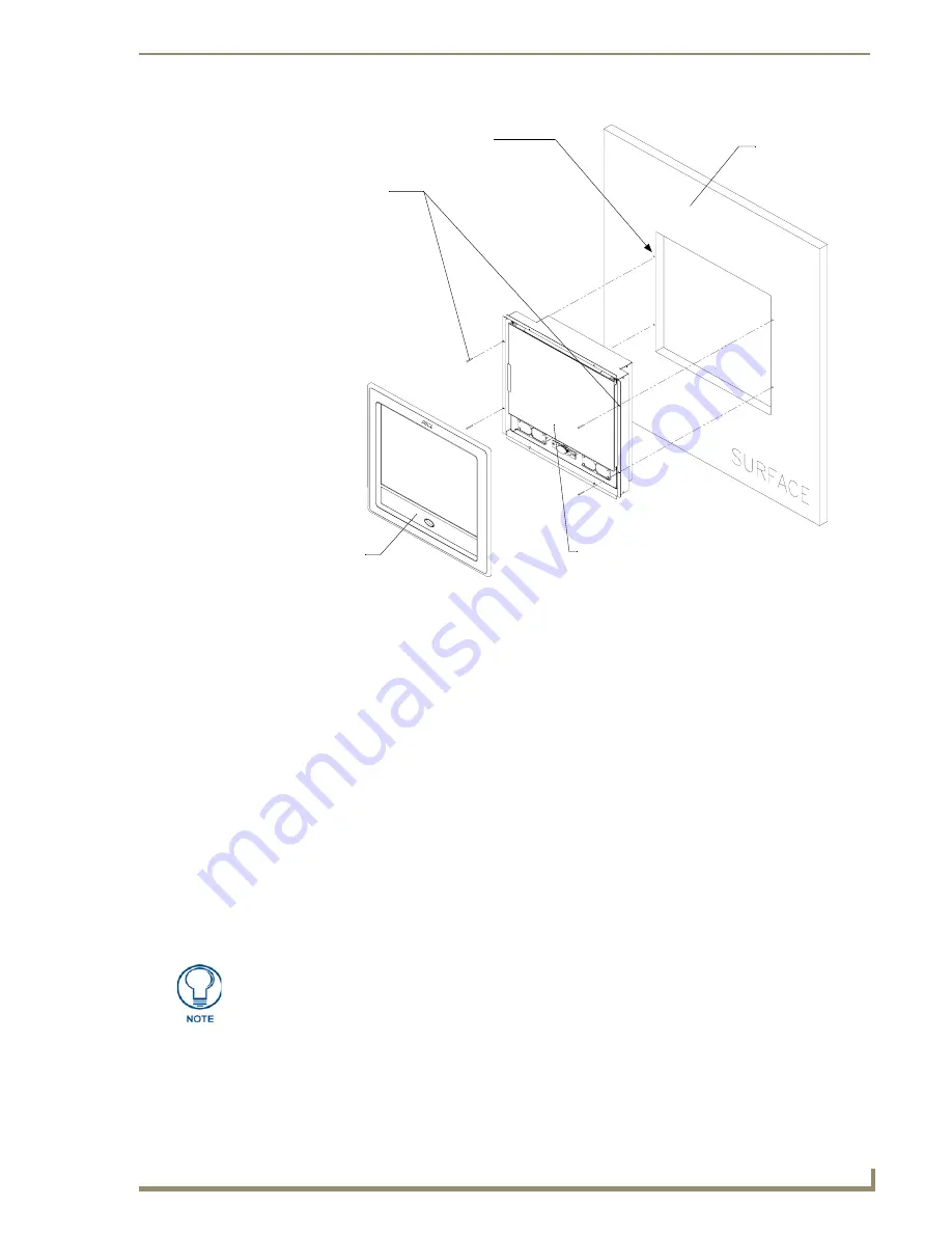
FIG. 45
Wall Mount panel installation configuration for flat/solid surfaces
B
- Main NXD unit consists of
Install the four (#4)
mounting screws
into the holes
(
screws not included
)
Flat surface
(can include a
the touch panel and housing
wall, podium, or
other flat
surface)
A -
Faceplate
(bezel)
Attachment is done
along the edges of
the cutout
Don’t disconnect the connectors from the touch panel. The unit must be installed with
the necessary connectors before being inserted into the equipment rack.
Содержание Modero NXD-CA12
Страница 20: ...Introduction 10 12 and 15 Modero Touch Panels...
Страница 60: ...Installation Procedures 12 and 15 Panels 50 12 and 15 Modero Touch Panels...
Страница 82: ...Configuring Communication 72 12 and 15 Modero Touch Panels...
Страница 90: ...Upgrading Modero Firmware 80 12 and 15 Modero Touch Panels...


