


Touch Panel Accessories
25
12” and 15” Modero Touch Panels
Step 2: Installing the Upgrade Compact Flash Card (NXD)
Complete the procedures outline within the
Step 2: Installing the Upgrade Compact Flash Card
section on
page 22 and then continue with the following Step 3.
Step 3: Replacing the NXD Outer Housing
1.
Once the card has been securely installed, gently place the outer housing back onto the metallic panel
casing (with the connector opening on the right-side of the panel) and align the four
pan-head Housing Screw holes along the edges of the outer housing.
2.
Gently place the outer housing back onto the metallic panel casing (with the connector opening on the
right-side of the panel) and align the four pan-head Housing Screw holes along the edges of the outer
housing.
3.
Insert and secure the four pan-head Housing Screws (FIG. 23) into the pre-drilled holes along the edges
of the NXD unit by using a grounded Phillips-head screwdriver.
4.
Reinstall the I/O connector plate by aligning all connectors to their respective locations.
5.
Secure the I/O connector plate using a grounded Phillips-head screwdriver and then twist the Stereo
Output nut back into the Stereo Output jack, as seen in FIG. 22.
Installation of the EXM memory module (Table Top Panel)
These procedures involves removing the outer housing, installing the new memory module, and then securely
replacing the outer housing back onto the NXT panel.
Step1: Removing the existing NXT Outer Housing
Complete the procedures outlined within the
Step1: Removing the existing NXT Outer Housing
section on
page 21.
Step 2: Installing the internal EXM memory module
1.
Discharge any static electricity from your body by touching a grounded metal object.
2.
Locate the existing Memory Module (FIG. 24) on the main board. For more detailed information on
component locations, refer to FIG. 19 on page 22 for Table Top panels and FIG. 23 on page 24 for Wall
Mount panels.
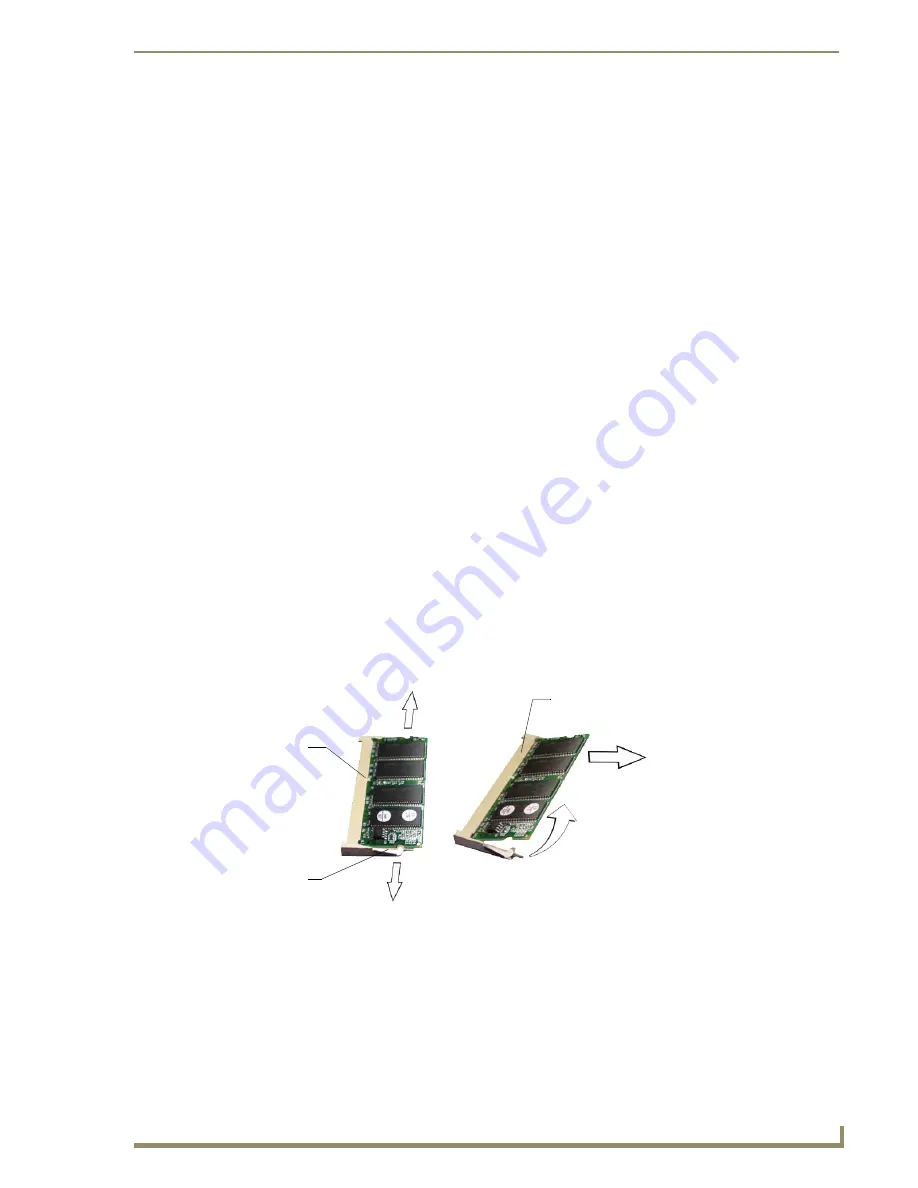
3.
Firmly grip the metallic braces (located on each side of the Memory Module) and pull them both
outwards until the previous module pops-up from the main board.
4.
Firmly clasp the existing Memory Module and pull it out at a 45° angle away from the connector location
on the main board.
5.
Remove the Memory Module upgrade from the anti-static bag.
6.
Firmly grasp the new Memory Module (
from the edges
) and insert the pins (at a 45° angle) into the
opening on the connector.
FIG. 24
Removing the Memory Module
Pull tabs outward
Module flips upwards
Pull memory
out at a 45° angle
Connector
Alignment
groove
Metallic
braces
Содержание Modero NXD-CA12
Страница 20: ...Introduction 10 12 and 15 Modero Touch Panels...
Страница 60: ...Installation Procedures 12 and 15 Panels 50 12 and 15 Modero Touch Panels...
Страница 82: ...Configuring Communication 72 12 and 15 Modero Touch Panels...
Страница 90: ...Upgrading Modero Firmware 80 12 and 15 Modero Touch Panels...


