262
Chapter 7 Plug-in Modules
44476B Microwave Switch Module
7
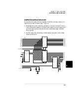
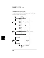
44476B Simplified Schematic
A simplified schematic of the 44476B is shown below. You must provide
your own microwave switches and mount them on the assembly. The
channel are numbered channels 00 and 01.
RELAY
K901
COM
NO
NC
+5
1
2
3
ORG
YEL
ORG
W1
CHANNEL 00
USER
INSTALLED
MICROWAVE
SWITCH
DRIVE
JUMPERS
FORM C
DRIVE RELAYS
RELAY
K903
COM
NO
NC
+5
1
2
3
CHANNEL 02
AVAILABLE
BUT NOT
USED
RELAY
K902
COM
NO
NC
+5
1
2
3
ORG
YEL
ORG
W1
CHANNEL 01
USER
INSTALLED
MICROWAVE
SWITCH
+5V
L901
C906
+5 TO DRIVE JUMPERS (YEL)
Содержание Agilent 3499A
Страница 13: ...1 1 Quick Start ...
Страница 27: ...2 2 Front Panel Operation ...
Страница 55: ...3 3 System Overview ...
Страница 77: ...4 4 Features and Functions ...
Страница 113: ...5 5 Remote Interface Reference ...
Страница 164: ...164 5 ...
Страница 165: ...6 6 Error Messages ...
Страница 173: ...7 7 Plug in Modules ...
Страница 256: ...256 Chapter 7 Plug in Modules 44475A Breadboard Module 7 ...
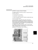
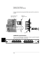
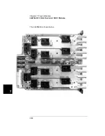
Страница 261: ...261 Chapter 7 Plug in Modules 44476B Microwave Switch Module 4 7 The 44476B is shown below ...
Страница 268: ...268 Chapter 7 Plug in Modules 44478A B 1 3 GHz Dual 4 to 1 MUX Modules 7 The 44478A B is shown below ...
Страница 286: ...286 Chapter 7 Plug in Modules Terminals and Connections Information 7 ...
Страница 288: ...288 7 ...
Страница 289: ...8 8 Application Programs ...
Страница 299: ...9 9 Specifications ...
Страница 343: ...343 Chapter 9 Specifications 44475A Breadboard Module 4 9 ...


