108
Chapter 4 Features and Functions
Error Conditions
4
Error Conditions
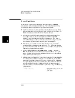
When an error occurs, the 3499A/B/C will beep and the ERROR
annunciator on the front-panel lights up. This indicates one or more
command syntax or hardware errors have been detected.
•
Up to 10 errors can be stored in the instrument error queue. Errors
are retrieved in a first-in-first-out (FIFO) manner, which means the
first error returned is the first error that was stored.
•
If more than 10 errors have occurred, the last error stored in the
queue (the most recent error) is replaced with “-350 QUEUE
OVERFLOW”. No additional errors are stored until you remove
errors from the queue. If no errors have occurred when you read the
error queue, the instrument responds with “NO ERROR”.
•
The error queue will be cleared automatically once you read the
queue, change the system mode, send the
*CLS
command, or cycle
power on the instrument. However, a module reset or an instrument
reset will not clear the error queue.
•
Front-Panel Operation: Press View, select “ERROR”, and press
Enter. The first error recorded is displayed. Use the arrow key to
scroll through the entire error message, then turn the knob to view
other errors in the error queue.
•
Remote Interface Operation: The errors can be returned as integers or
as variant values. When an integer value is returned, you need to
associate the integer value with the error (refer to “Error Messages”
on page 165). If you return a variant value, the error number and
error string are returned. To detect when errors occur using the
remote interface, use the SCPI status system (see page 148 for more
information).
SYSTem:ERRor?
! Query the error queue for the
first error.
Содержание Agilent 3499A
Страница 13: ...1 1 Quick Start ...
Страница 27: ...2 2 Front Panel Operation ...
Страница 55: ...3 3 System Overview ...
Страница 77: ...4 4 Features and Functions ...
Страница 113: ...5 5 Remote Interface Reference ...
Страница 164: ...164 5 ...
Страница 165: ...6 6 Error Messages ...
Страница 173: ...7 7 Plug in Modules ...
Страница 256: ...256 Chapter 7 Plug in Modules 44475A Breadboard Module 7 ...
Страница 261: ...261 Chapter 7 Plug in Modules 44476B Microwave Switch Module 4 7 The 44476B is shown below ...
Страница 268: ...268 Chapter 7 Plug in Modules 44478A B 1 3 GHz Dual 4 to 1 MUX Modules 7 The 44478A B is shown below ...
Страница 286: ...286 Chapter 7 Plug in Modules Terminals and Connections Information 7 ...
Страница 288: ...288 7 ...
Страница 289: ...8 8 Application Programs ...
Страница 299: ...9 9 Specifications ...
Страница 343: ...343 Chapter 9 Specifications 44475A Breadboard Module 4 9 ...


