5
The Display at a Glance
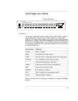
The display is divided into several areas. The channel and slot number is
always displayed on the right corner of the display. The main area,
which is in the center of the display, is primarily used to display channel
status (open or closed), information messages, menu items, prompt infor-
mation, error messages, and so on. Around the display are annunciators
to indicate various states of the instrument operation. The annunciators
are summarized below.
Other annunciators in the display are not used in the Agilent 3499A/B/C
system.
Channel/Slot Number
Annunciators
Annunciator
Indication
SCAN
Scan is initiated.
MON
Instrument is in monitor mode.
VIEW
Scan list, errors or relay cycle counts are being viewed.
CONFIG
Any configuration key has been pressed.
*
Instrument is advancing a scan step.
ADRS
Instrument is active on the remote interface.
RMT
Instrument is in remote mode.
ERROR
Error queue is not empty.
EXT
Scan is waiting for external trigger source.
SHIFT
Shift key has been pressed.
Содержание Agilent 3499A
Страница 13: ...1 1 Quick Start ...
Страница 27: ...2 2 Front Panel Operation ...
Страница 55: ...3 3 System Overview ...
Страница 77: ...4 4 Features and Functions ...
Страница 113: ...5 5 Remote Interface Reference ...
Страница 164: ...164 5 ...
Страница 165: ...6 6 Error Messages ...
Страница 173: ...7 7 Plug in Modules ...
Страница 256: ...256 Chapter 7 Plug in Modules 44475A Breadboard Module 7 ...
Страница 261: ...261 Chapter 7 Plug in Modules 44476B Microwave Switch Module 4 7 The 44476B is shown below ...
Страница 268: ...268 Chapter 7 Plug in Modules 44478A B 1 3 GHz Dual 4 to 1 MUX Modules 7 The 44478A B is shown below ...
Страница 286: ...286 Chapter 7 Plug in Modules Terminals and Connections Information 7 ...
Страница 288: ...288 7 ...
Страница 289: ...8 8 Application Programs ...
Страница 299: ...9 9 Specifications ...
Страница 343: ...343 Chapter 9 Specifications 44475A Breadboard Module 4 9 ...

